
 EN
What Makes Electric Control Valve Vital For Digital Lines?
On a digital process line, a control command has no value until it produces repeatable movement at the final control element. That is why an electric control valve can be central to the line rather than merely an accessory. It connects the control system’s output to a physical change in flow, pressure, level, temperature, or another process variable. The important question is not whether automation is fashionable; it is whether the valve, actuator, signal interface, and process duty work as one controllable chain.
From an automation-control perspective, start with the process objective. An electric control valve may be used for open/close duty, modulating duty, or a sequence that must report its state to a PLC, DCS, or other supervisory system. Those applications are not interchangeable. A valve selected only by line size can still become the weak point if the required travel, torque, response behavior, feedback, or fail-state logic has not been confirmed.
The electric control valve completes the digital control loop
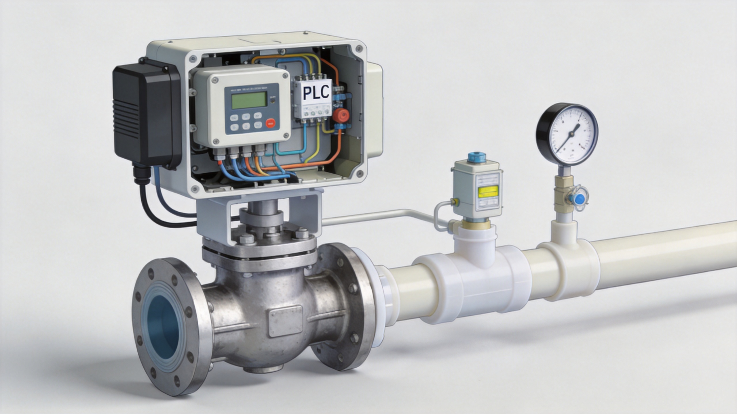
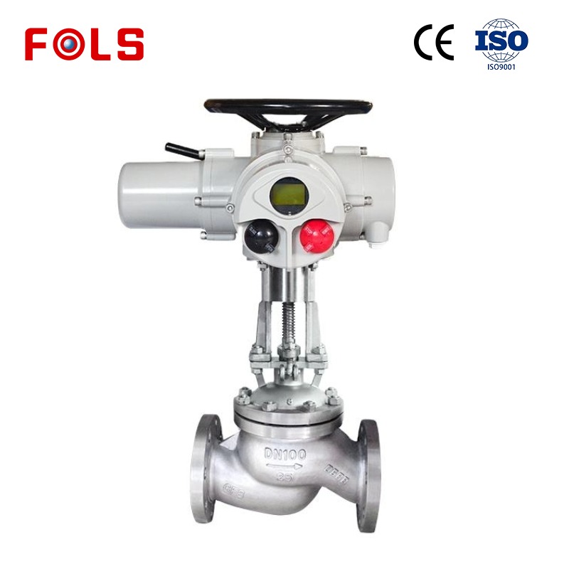
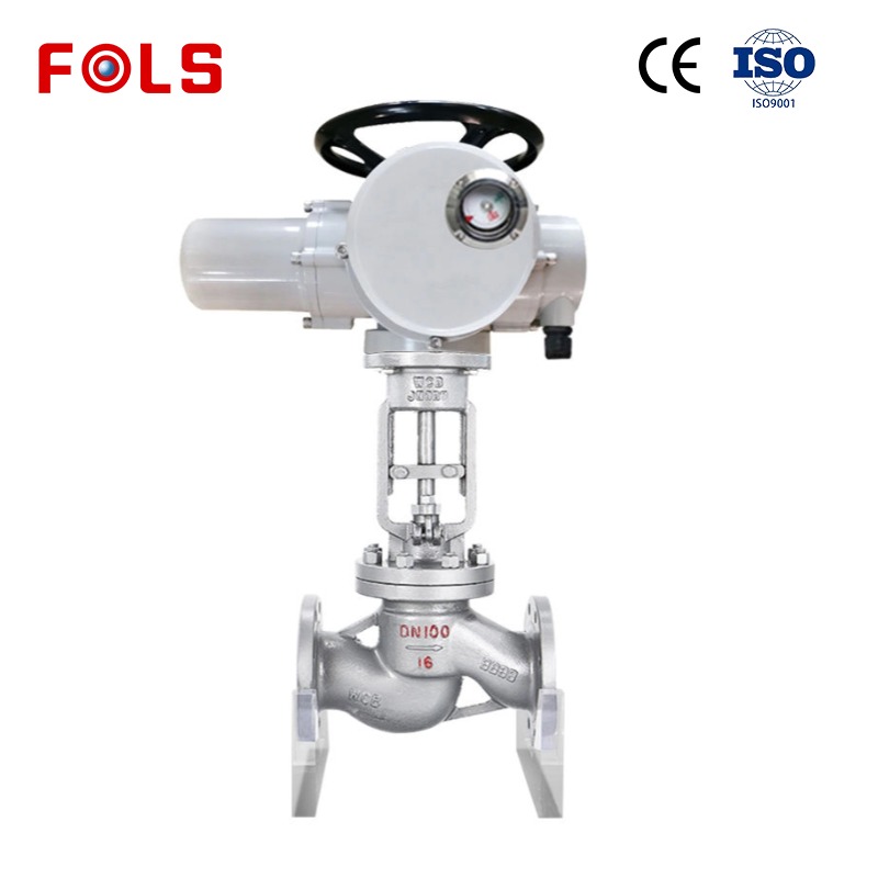
A digital line typically has a measurement, a controller, an output command, and a final element that changes the process. The electric control valve belongs at that last stage. Its actuator converts an electrical command into mechanical motion, allowing the valve to move toward an intended position. In a modulating service, the controller may vary the command as the measured condition changes; in an on/off service, the same control architecture may need dependable proof that the commanded state was reached.
This is the practical distinction between a valve that is automated and a valve that is useful in a digital line. The system needs more than a motor mounted on a valve body. It needs an understandable command path and, where the application calls for it, a usable indication of actual travel. Valve motion can be affected by load, friction, process forces, mechanical setup, and electrical supply conditions. The specification should therefore state what the control system must know and what the valve assembly can actually report.
Why feedback and status visibility matter
For many process duties, feedback reduces uncertainty between the requested position and the observed valve position. A digital controller can issue a command, but operators and maintenance teams still need a way to investigate a mismatch. Position indication, limit feedback, alarms, and supported device diagnostics can make that investigation more structured. They do not prove that every process problem is caused by the valve, and they do not remove the need for commissioning, but they make the final element less opaque.
That visibility matters when a line is expected to react consistently across shifts, recipes, or operating modes. It also helps separate a control issue from a mechanical or wiring issue. For example, if a command is present but movement is incomplete, the next check may involve available torque, travel limits, valve load, wiring, or the configured control signal. A vague instruction to “check the valve” is less useful than a defined path from command to feedback.
Modulating flow needs more than nominal pipe size
A proportional water flow control valve is a useful example. The buyer may want a digital signal to produce a predictable change in water flow, but the result depends on the complete assembly: valve characteristic, pressure differential, piping conditions, actuator resolution, control strategy, and the process measurement used by the loop. Equal nominal diameter does not guarantee equal regulating behavior. Flow range, required turndown, cavitation risk, material compatibility, and required control accuracy should be clarified before selecting the valve body and actuator.
In other words, the electric control valve should be evaluated as part of a loop, not as an isolated catalog line. Where a water process must hold a flow target, the engineering conversation should cover whether the valve is intended for throttling, how often it will adjust, and how the controller will interpret feedback. A well-defined requirement makes it easier to compare possible valve and actuator combinations without promising a result that has not yet been validated on the actual system.
Electric actuation and pneumatic actuation solve different constraints
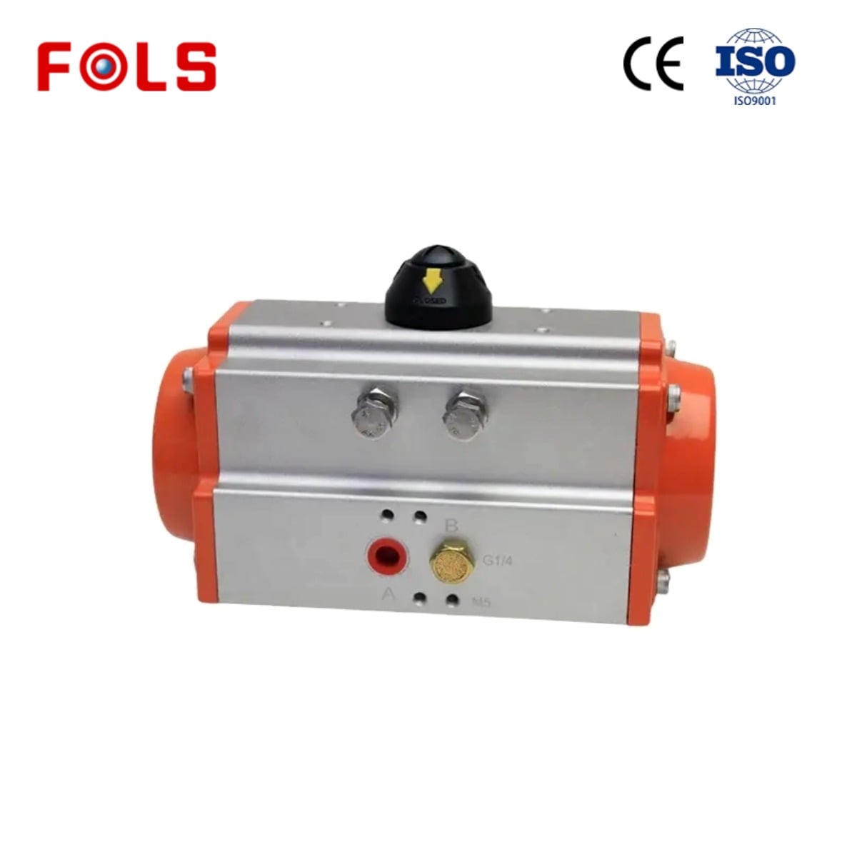
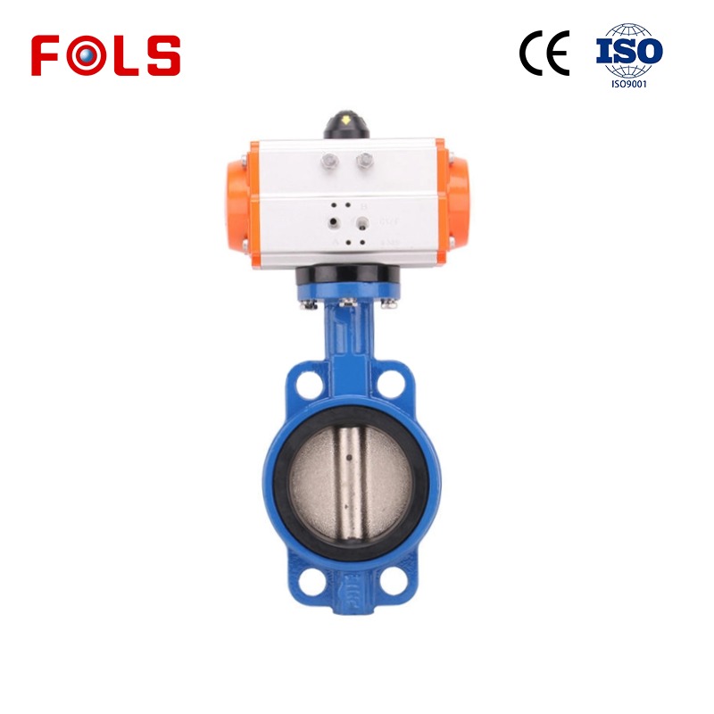
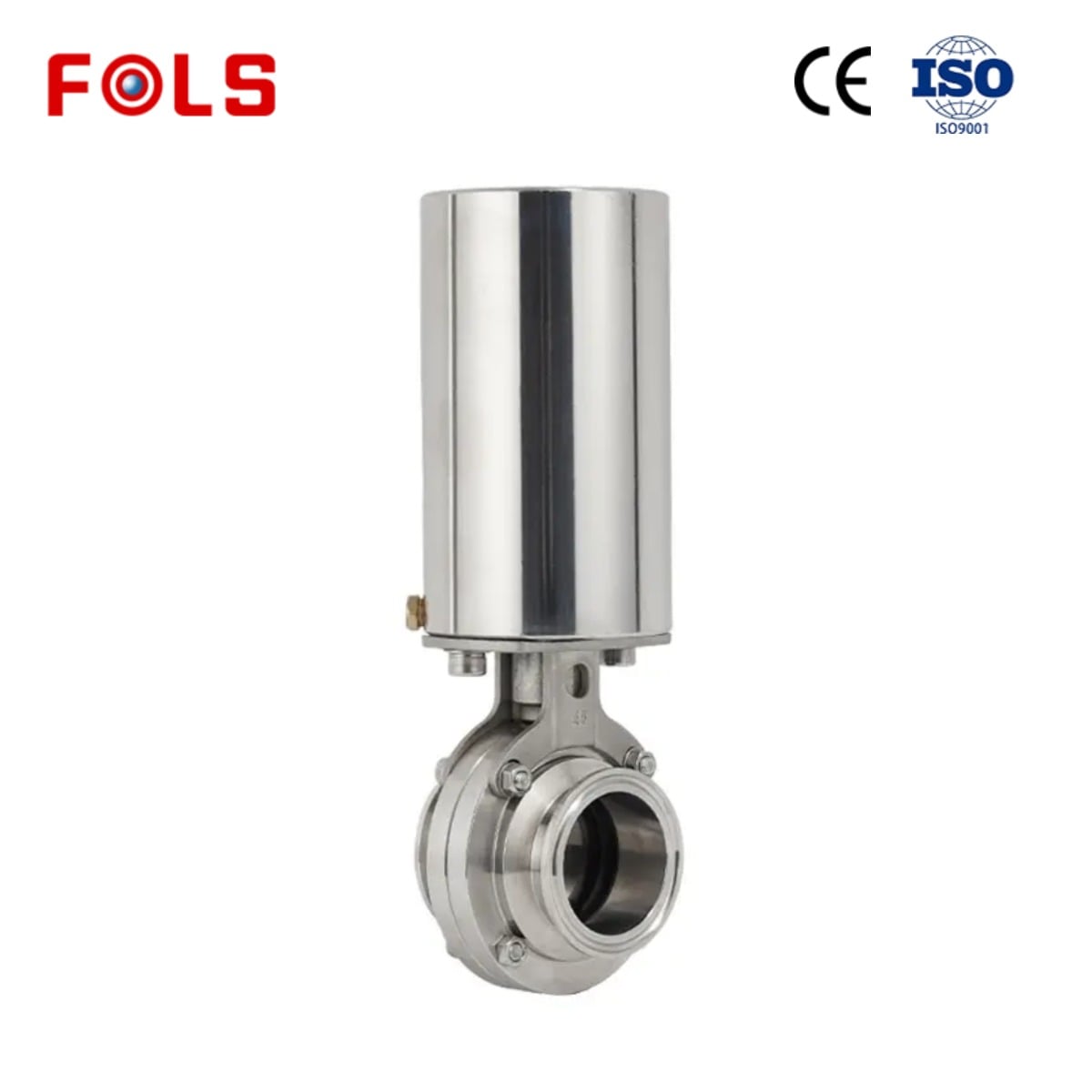
An electric solution is not automatically preferable to every pneumatic actuator with positioner. The better choice depends on utilities, response expectations, fail action, environment, maintenance practice, and the control architecture. A pneumatic actuator with positioner uses air and position feedback to move toward a commanded position; it can be appropriate where plant air, established pneumatic practices, or a particular fail-action philosophy are already part of the design.
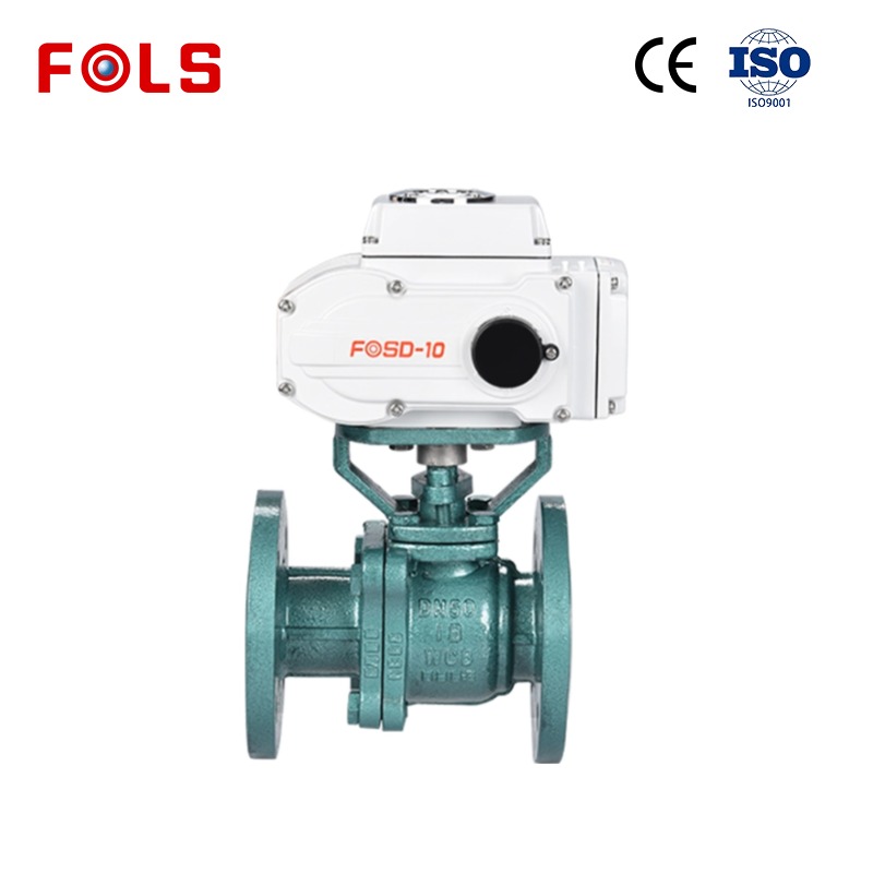
An electric control valve may be attractive where electrical power and digital integration are the more direct fit, or where the project wants fewer pneumatic components at that location. But the decision must account for the actual duty cycle and failure behavior. Ask whether the process needs the valve to stay, close, open, or move to another defined state on loss of power or signal. That requirement cannot be inferred from the phrase “digital line,” and it should not be left until after installation.
Digital diagnostics support maintenance decisions, not shortcuts
Some digital valve devices are designed to run, analyze, and store diagnostic tests. When that capability is specified and correctly commissioned, it can give maintenance teams more context than a basic command-only installation. Trends or alerts may help a team decide when to inspect the assembly, verify travel, or review mechanical resistance. Still, diagnostics should be treated as a supported tool, not as a guarantee of fault-free operation or a substitute for a site maintenance plan.
A useful working rule is this: the valve is only one part of the chain; the actuator, feedback device, cabling, controller configuration, and process conditions belong in the same review. Treating an actuator as a bolt-on item often leaves a gap around stroke limits, signals, and abnormal-state behavior. That gap may only become obvious during startup, when changes are more expensive and less convenient.
A practical specification checklist
Before specifying an electric control valve for a digital line, organize the conversation around the items below:
- Process duty: medium, flow range, pressure, temperature, solids or corrosive content, and whether the function is on/off or modulating.
- Valve and trim: valve style, size, connection, materials, sealing, flow characteristic, and allowable pressure conditions.
- Actuation: required torque or thrust, travel time, duty cycle, manual override needs, and the required state after a power or signal interruption.
- Controls: available power, command type, feedback signals, communication needs, interlocks, alarms, and the controller that will receive them.
- Verification: commissioning steps, travel calibration, documentation, and the tests that must be completed before the assembly is accepted.
For a proportional water flow control valve, add the target flow range and differential-pressure conditions. For a pneumatic actuator with positioner, add air supply quality, available pressure, and the required loss-of-air action. The same disciplined approach helps the project compare electric and pneumatic paths on relevant facts rather than on a generic preference.
Make the valve data usable to the people who run the line
For industrial buyers, the strongest electric control valve discussion is usually a requirements discussion. FOLS Valve works with electric actuators, pneumatic valves, and automatic control systems for industrial applications, so a technical conversation can begin with the conditions that determine compatibility rather than an unsupported claim that one configuration suits every line. A supplier should be able to distinguish known requirements from items that still need engineering confirmation.
Start by documenting the medium, pipe size, pressure and temperature, required flow or switching function, available power or air, desired control and feedback signals, environmental constraints, and fail-state expectation. With those facts visible, the digital line has a better chance of receiving a valve assembly that can be integrated, commissioned, and maintained with fewer avoidable questions.
Conclusion
An electric control valve is vital for a digital line because it translates digital intent into controlled physical action while making the final control element easier to integrate and assess. Its value comes from the complete loop: a correctly matched valve body, suitable electric actuator, appropriate command and feedback, and clear operating requirements. Define those elements early, then validate them against the actual process. That is a more reliable route to controllable flow than choosing by valve name alone.
 Hot News





