
 EN
How Does Hydraulic Control Valve Manage High Forces?
A Hydraulic Control Valve manages high forces by controlling pressurized fluid, not by creating force on its own. In a hydraulic circuit, the pump supplies flow, the cylinder or motor converts pressure and flow into motion, and the valve decides where the fluid goes, how quickly it moves, and when pressure must be limited. That division of work is why a compact control element can govern equipment that moves heavy loads.
From an automation-control perspective, the useful question is not simply “how strong is the valve?” It is whether the valve, actuator, pressure setting, fluid path, and control signal are matched to the required force and operating sequence. A Hydraulic Control Valve is part of the control chain; cylinder area and system pressure establish the available linear force.
Pressure and Area Create the Available Force
The basic relationship is force = pressure × effective area. Pascal’s principle describes why pressure in a confined fluid is transmitted through the system. A relatively small command force can therefore control a much larger working force when pressurized oil acts on a larger piston area. This does not violate energy conservation: the larger-force side moves a shorter distance for a given fluid volume, and the pump remains the energy source.
For a cylinder, the available extension force is commonly estimated from pressure and bore area. The real usable force is lower than the ideal calculation after friction, seal drag, backpressure, mechanical losses, and load geometry are considered. That is why a Hydraulic Control Valve should be selected with the complete circuit in mind rather than from a pressure number alone.
What the Valve Actually Controls
A Hydraulic Control Valve generally performs one or more of four jobs:
- Route flow: directional sections send oil to one side of a cylinder or to a hydraulic motor, then return fluid to tank or another circuit path.
- Start, stop, or reverse motion: spool position determines whether an actuator extends, retracts, holds, or changes direction.
- Set motion speed: flow-control functions regulate how much oil reaches an actuator per unit of time. More flow normally means a higher actuator speed, subject to load and circuit design.
- Limit or manage pressure: relief, reducing, sequence, counterbalance, or load-holding functions protect the circuit or control how a load behaves.
These functions interact. Saying that a valve “handles high force” is incomplete unless it also states the pressure limit, the cylinder area, the load direction, and the required fail-safe behavior.
Directional Control Turns Hydraulic Power into Useful Motion
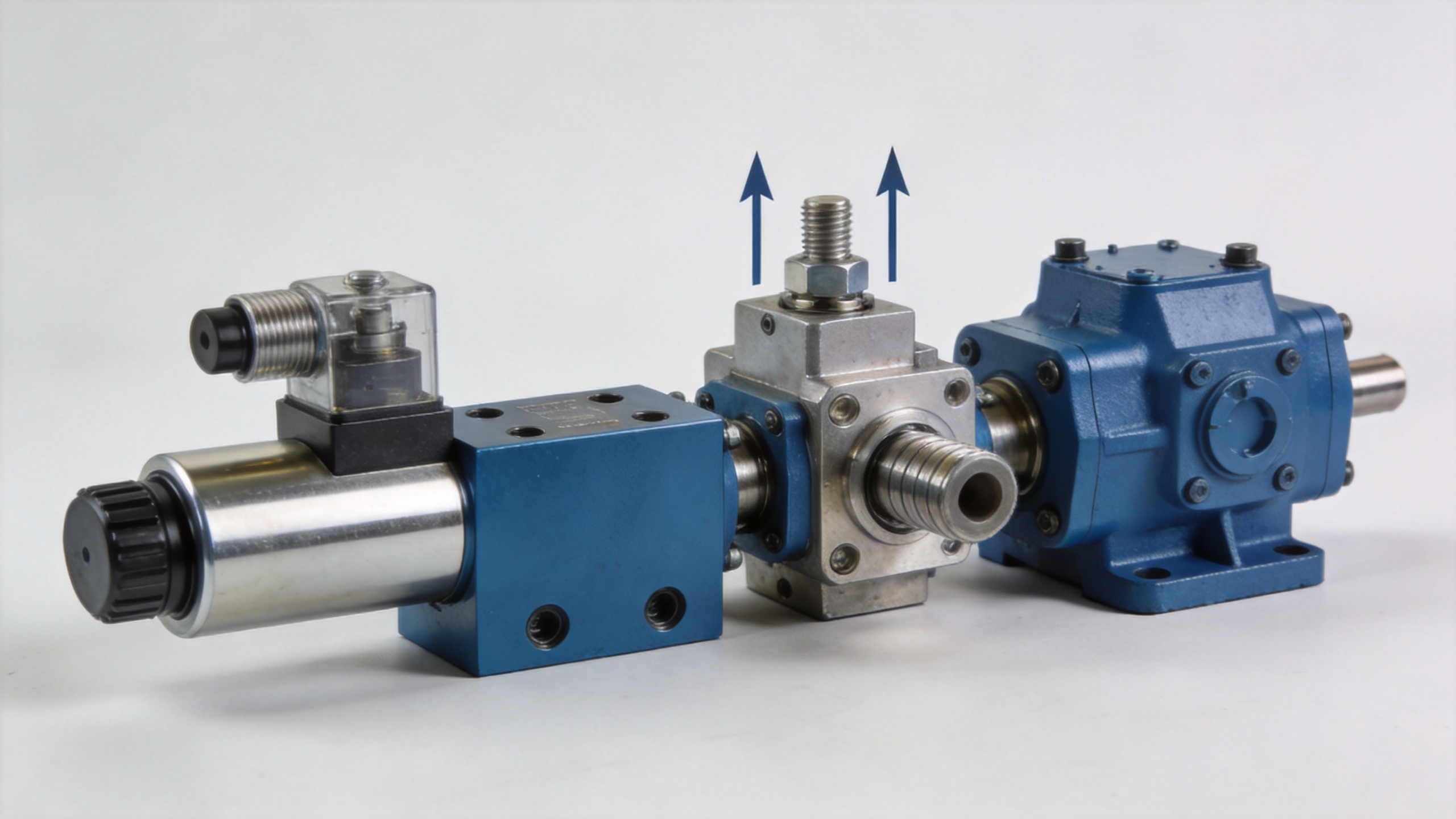
A directional Hydraulic Control Valve uses a spool, poppet, or cartridge arrangement to connect pump, work, and return passages in a defined pattern. When a spool shifts, it can send pressurized oil to the cap end of a cylinder and allow oil from the rod end to return. Reversing the spool reverses those paths and retracts the cylinder.
In this role, the valve is an organizer of hydraulic power. It determines the motion command, while the pump and cylinder determine how much hydraulic power and force are available. For high-force applications, passage sizing, allowable pressure drop, spool leakage, and response behavior matter because excessive restriction can generate heat and reduce available pressure at the actuator.
Valve size alone does not guarantee good control. A larger valve may reduce restriction, but the required flow, hose layout, load inertia, contamination control, and the actuator’s effective area still need to be checked together.
Pressure-Control Functions Keep Force Within a Safe Range
Because force rises with pressure, pressure-control functions are central to managing high loads. A relief valve establishes a maximum circuit pressure path so the pump is not forced to continue raising pressure against a blocked or overloaded condition. Reducing valves can provide a lower controlled pressure to a branch circuit. Sequence valves can delay a secondary movement until a chosen pressure condition is reached.
For suspended or overrunning loads, a counterbalance or load-holding arrangement may be needed to prevent unintended movement. The correct arrangement depends on the machine function and the load path. A directional valve by itself is not automatically a load-holding device, so the failure mode must be reviewed before assuming a cylinder will stay in position.
ISO 4413:2010 is a system-level reference for general rules and safety requirements for hydraulic fluid power systems and components used on machinery. It is not a product-compliance claim here; it is a reminder that control-power loss, pressure release, maintenance access, and hazardous motion must be considered at the circuit level.
How Electronic and Pilot Commands Scale the Control Task
The command side of a Hydraulic Control Valve may be manual, mechanical, pilot-operated, or solenoid-actuated. A small electrical signal can energize a solenoid, move a pilot stage, and shift a larger main spool. This is a control amplification path, not a creation of hydraulic energy. The hydraulic supply still provides the work capability.
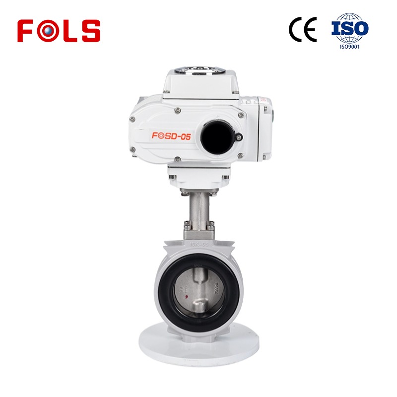
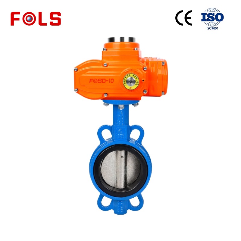
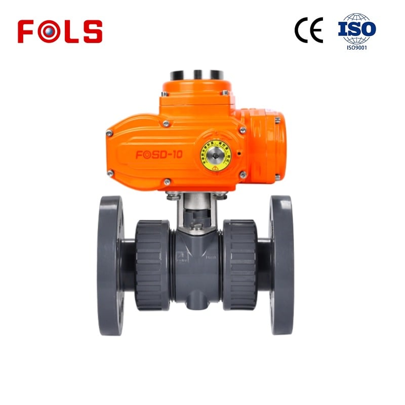
That distinction is useful when comparing hydraulic control with electric water valves. Electric water valves often use an actuator to open or close a flow path directly in lower-force fluid service. A hydraulic circuit can use a small electrical command to control a larger hydraulic stage, allowing the system to direct high-pressure oil to a cylinder or motor. The appropriate choice depends on the medium, pressure, duty cycle, required response, and safety requirements.
A hydraulic diverter valve 12v is another example of command-versus-power separation. The 12 V coil can shift or pilot a valve section, but its suitability still depends on the rated hydraulic pressure, flow capacity, internal configuration, voltage tolerance, connector protection, and the load behavior after power is removed.
Key Selection Checks for High-Force Circuits
Before specifying a Hydraulic Control Valve, build a concise information list:
- Required load force, travel direction, duty cycle, and acceleration or deceleration needs.
- Available pump flow and normal versus maximum system pressure.
- Cylinder bore, rod diameter, stroke, and whether force is required on extension, retraction, or both.
- Fluid type, temperature range, cleanliness target, and material or seal compatibility.
- Valve function: directional, relief, reducing, sequence, proportional, load holding, or a combination.
- Command method and failure position: manual, solenoid, pilot, spring return, center condition, and emergency behavior.
- Porting, pressure drop, heat generation, service access, and documentation to be confirmed.
In practice, a single pressure number is meaningful only when it is tied to a cylinder area and a known operating condition. Likewise, a high flow rating is not enough if the chosen center configuration or load-control arrangement does not support the intended motion.
Conclusion: The Valve Manages Energy; the Circuit Produces Force
A Hydraulic Control Valve manages high forces by directing pressurized fluid to the correct actuator, controlling motion and speed, and coordinating pressure-limiting or load-control functions. The available force comes from hydraulic pressure acting over actuator area, while the valve makes that force useful, repeatable, and safer to manage.
For a reliable selection, start with the load, cylinder dimensions, pressure range, flow requirement, and failure behavior. Then compare the valve’s directional paths, pressure-control functions, actuation method, and allowable pressure drop against those conditions. That approach is more dependable than choosing from a product name or nominal pressure rating alone.
 Hot News





