
 EN
Electric Actuator in Modern Flow Control Systems
In a modern flow-control loop, a valve is only as responsive as the device that moves it. An Electric Actuator converts electrical power and a control command into valve movement, helping operators automate isolation, modulation, and position feedback without depending on a plant air supply. From an automation-control adviser’s perspective, the useful question is not simply whether an actuator is electric. It is whether the valve, process conditions, control signal, mounting interface, and maintenance plan work together.
This distinction matters because an actuator is not an accessory to be chosen after the valve. It is part of the final control assembly. A good specification creates a traceable path from process requirement to installed behavior; a weak one can leave torque, duty cycle, environmental protection, or feedback functions unresolved until commissioning.
What an Electric Actuator Does in a Flow-Control Loop
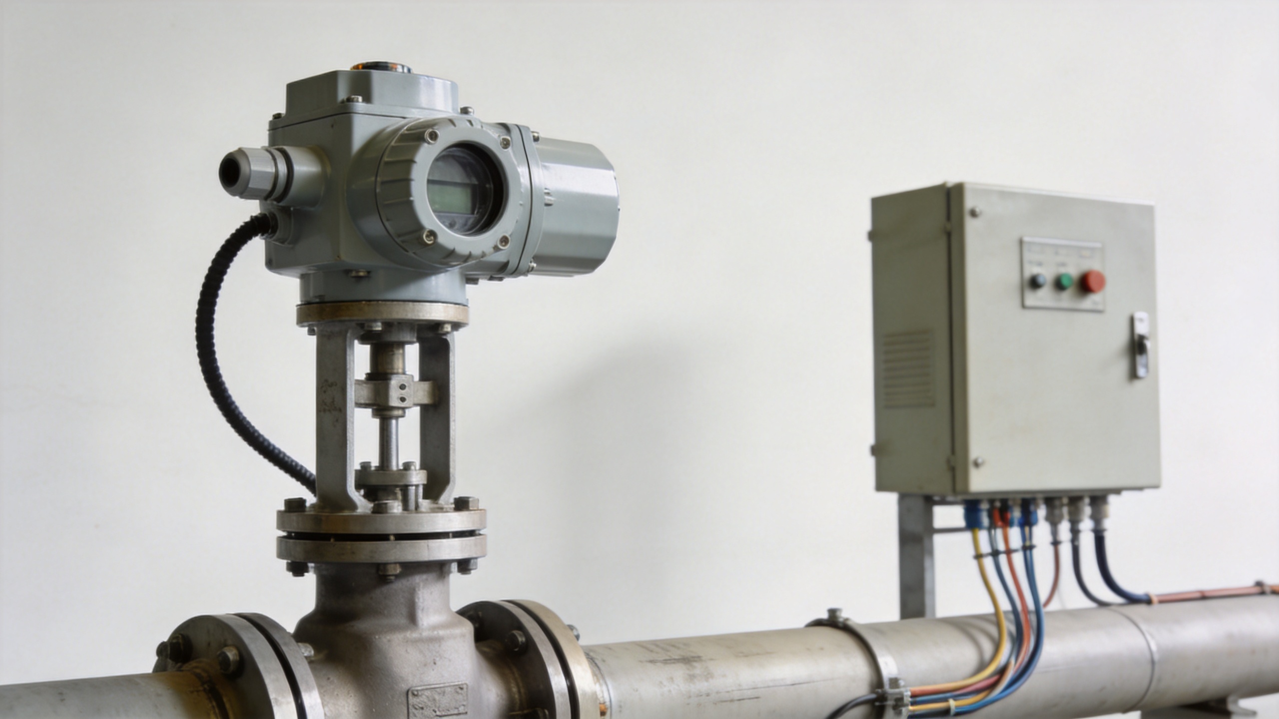
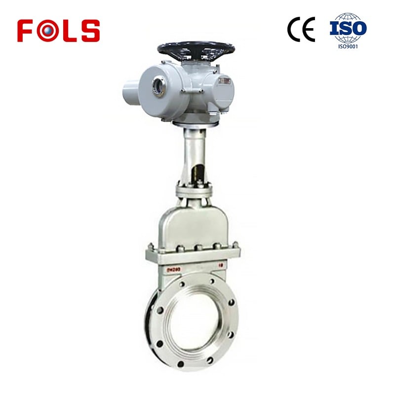
An Electric Actuator uses a motor, gearing, controls, and an output mechanism to turn or position a valve. On quarter-turn valves, the output typically rotates the stem through a defined angle. On multi-turn valves, it drives repeated stem rotation. Depending on the configuration, the actuator may receive a simple open/close command, a modulating signal, or a networked command and return a status or position signal to the control system.
That capability lets the flow-control loop connect field equipment with PLC, DCS, or local control logic. Still, “electric” does not automatically mean precise control. Resolution, repeatability, speed, torque behavior, limit settings, and the valve’s own flow characteristic all influence the result. For throttling service, the valve and actuator must be evaluated as one assembly rather than as separate catalog selections.
Why Electric Actuation Is Used More Often
An Electric Actuator can be attractive where electrical power and control wiring are easier to provide or maintain than clean, reliable instrument air. It can also simplify installations that need local indication, remote commands, configurable travel limits, or feedback to a supervisory system. These are practical advantages, not universal rules: a pneumatic solution may still be appropriate where fast cycling, a plant air architecture, or a particular fail-action philosophy drives the design.
The decision should therefore begin with the operating scenario. Is the valve mostly an on/off isolation point, a frequently adjusted modulating device, or an emergency-related function? How quickly must it move? What must happen after a loss of power? Those answers frame the actuator choice more reliably than a preference for one energy source.
Start Selection with the Valve and Process Conditions
A robust Electric Actuator selection starts with the valve’s real operating torque or thrust requirement, including breakaway and seating conditions where applicable. Nominal valve size alone is not enough. Differential pressure, media characteristics, temperature, seal friction, deposits, cycling history, and stem or packing condition can change the force required in service.
Ask for a documented valve torque or thrust basis at the relevant process conditions, then verify the actuator output across the portion of travel that matters. Adding an unexplained safety factor is not a substitute for understanding the load. An oversized unit can introduce its own issues, while an undersized unit may stall, trip, or fail to achieve repeatable shutoff.
- Valve behavior: valve type, travel, stem arrangement, breakaway and seating demands, and intended control duty.
- Process envelope: medium state, pressure differential, temperature, solids, corrosion potential, and whether these conditions vary.
- Mechanical interface: mounting pattern, coupling, allowable thrust or side load, handwheel access, and clearance around the valve.
- Electrical and controls: supply voltage, command type, feedback requirement, cable routing, local controls, and integration responsibility.
This checklist also prevents a common shortcut: treating every valve of the same nominal size as needing the same actuator. The same valve family can behave differently when its medium, pressure differential, or operating frequency changes.
Match Duty Cycle, Speed, and Control Mode
Torque answers how much output is needed; duty cycle addresses how often and how long the Electric Actuator can operate within its rated limits. A device that is suitable for occasional isolation may not be suitable for continual repositioning. Confirm the supplier’s rated duty cycle against the expected command pattern, including startup, normal operation, testing, and abnormal operating sequences.
Speed deserves the same discipline. A short stroke time may be beneficial in some process responses, but it can increase mechanical stress or make stable control harder if the valve characteristic and loop tuning are not aligned. Conversely, a deliberately slower actuator may be entirely adequate for a noncritical isolation point. The required response should be written as a process need, not inferred from a generic “fast” or “slow” label.
For modulating service, specify the input and feedback arrangement clearly. Common requirements include analog commands, discrete open/close signals, position feedback, and communications interfaces. An electronic air pressure regulator may be relevant in a pneumatic control architecture, but it serves a different control path from a motorized valve operator. Comparing the two at the signal-and-energy level helps teams avoid mixing an air-pressure-control component into an electric-actuation specification.
Protect the Assembly from Its Installation Environment
Environmental suitability is a system question. The actuator enclosure, cable entries, connectors, local controls, and mounting orientation all need to suit the installation. IEC 60529 provides the well-known IP classification framework for enclosure protection against dust and water ingress, but the required rating should be tied to the actual location and verified for the supplied configuration.
For example, an indoor dry service and a washdown, coastal, dusty, or outdoor location create different risks. Temperature extremes, condensation, vibration, hazardous-area requirements, and access for inspection can matter as much as the headline enclosure rating. Avoid assuming that a stated IP code answers every environmental question; confirm the applicable documentation, options, and installation constraints.
Electric Actuator and Pneumatic Gate Valve: Compare the Whole Architecture
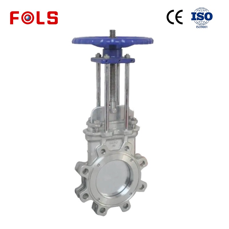
A pneumatic gate valve describes a valve assembly driven by compressed air, while an Electric Actuator describes an electrically powered drive approach that can be fitted to compatible valve types. They should not be treated as direct, one-line substitutes without first defining the valve function, travel, fail position, cycle rate, available utilities, and maintenance capability.
| Decision area | Questions for an electric approach | Questions for a pneumatic approach |
|---|---|---|
| Utility availability | Is stable electrical supply and protected wiring available? | Is clean, reliable instrument air available at the point of use? |
| Control integration | Which command, feedback, local-control, and communication functions are required? | What solenoids, positioners, or air-pressure-control components are required? |
| Failure behavior | What should occur on loss of power, and what mechanical or electrical provision supports it? | What should occur on loss of air, and how is the spring or air-volume design verified? |
| Maintenance | Can teams inspect wiring, seals, gearing, and travel settings safely? | Can teams maintain air quality, tubing, fittings, and pneumatic accessories? |
The point is not to declare a winner. It is to make unknowns visible before procurement. A pneumatic gate valve may suit a site whose air system and fail-action requirements are already established. An electric arrangement may suit another site where electrical integration and position reporting are the clearer path. Both require validation against the actual valve and process.
Commissioning and Maintenance Keep Control Reliable
Commissioning should document more than a successful open/close test. Verify travel limits, rotation direction, local and remote commands, interlocks, feedback scaling, alarm behavior, and the response to credible utility-loss scenarios. If the assembly will modulate, test it within an approved process-safe condition and record the settings used.
After startup, maintenance should look for changes that can alter demand on the Electric Actuator: rising valve friction, packing adjustment, corrosion, water ingress, loose connections, unusual heat, or changes in cycling frequency. Automation does not remove maintenance; it changes which components must be inspected. A simple baseline record from commissioning makes later diagnosis far more useful.
A Practical Specification Path
- Define the valve function: isolation, modulation, or another controlled movement.
- Document process conditions and the valve torque or thrust basis across the relevant travel.
- Select the Electric Actuator output, travel, speed, duty cycle, and mounting arrangement against that basis.
- Specify power, commands, feedback, local controls, and control-system ownership.
- Match the enclosure and accessory configuration to the installed environment, then verify supporting documentation.
- Agree commissioning tests, maintenance access, spares, and records before the equipment reaches site.
When these details are confirmed early, an Electric Actuator becomes a manageable part of a modern flow-control system rather than a late-stage compatibility problem. The next useful action is to assemble the valve data, operating sequence, utilities, and interface requirements in one reviewable specification before final selection.
 Hot News





