
 EN
Where Should Electric Control Valve Be Deployed?
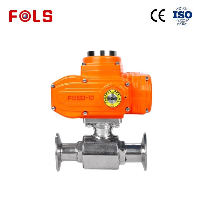
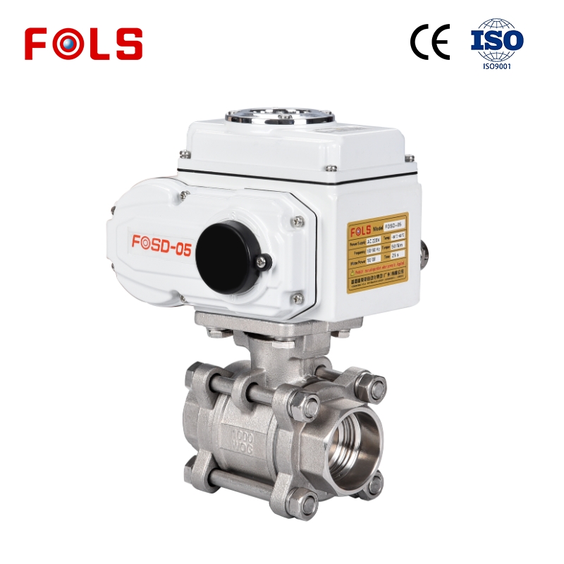
An electric control valve belongs where a process needs a repeatable valve position from an electrical command—not simply where automation sounds attractive. From an automation-control consultant’s viewpoint, the first question is not “Which valve is appropriate?” but “What must the line do, under which operating conditions, and how will the control system command it?” That sequence helps engineers and buyers place an electric control valve in applications where it can improve consistency without assuming that every pipe needs the same solution.
Start With the Control Duty, Not the Valve Name
A sensible location for an electric control valve is a line where the process benefits from controlled opening, closing, or positioning. In an on/off duty, the actuator receives a simple open or close instruction. Typical examples include isolation before a cleaning cycle, switching a utility branch, or sequencing a tank fill. In a modulating duty, the electric control valve changes position in response to a proportional control signal so that flow, level, pressure, or temperature can be managed within a process loop.
That distinction matters in practice. A valve that is adequate for infrequent isolation may not be the right electric control valve for frequent throttling. Before deployment, document whether the intended action is two-position, stepped, or continuously modulating; the expected cycle frequency; the required response time; and the consequence of a valve failing to move. These details affect the valve trim, actuator torque or thrust, control interface, and maintenance plan together.
Common Places to Deploy an Electric Control Valve
1. Utility distribution branches
An electric control valve is often practical on water, treated-water, cooling-water, and compatible utility branches when a PLC, building-management system, or local panel must control availability remotely. The deployment point should still be selected around the process purpose: use it to isolate a branch, balance a defined flow path, or sequence equipment—not merely to replace every manual valve. Media quality, pressure, temperature, valve material, and available electrical supply need confirmation before specification.
2. Tank filling, transfer, and level-related operations
Where a tank requires repeatable fill sequencing or a level controller must influence incoming flow, an electric control valve can form part of the control layer. In a simple batch process, on/off operation may be sufficient. In a process requiring smoother level regulation, a modulating actuator and suitable valve characteristic may be needed. Do not treat the actuator as an accessory: the valve body, sizing assumptions, actuator travel, feedback signal, and control logic must work as one system.
3. HVAC and thermal-management loops
Heating, cooling, and thermal-management circuits are frequent candidates for an electric control valve because they may need scheduled operation or a response to temperature demand. A correctly located valve can regulate a coil branch, isolate a zone, or support equipment sequencing. However, a deployment decision should consider the medium, differential pressure, required close-off capability, and the amount of maintenance space around the valve. A crowded installation that prevents actuator access can turn an otherwise sensible automation choice into a service problem.
4. Process skids and packaged equipment
Packaged filtration, dosing, treatment, mixing, and transfer skids can use an electric control valve when the skid controller needs a defined, repeatable valve action. This placement is especially useful when electrical wiring is already part of the skid design and the operating sequence is known. It is not enough to copy a valve specification from another project, though. The same nominal valve can behave differently when fluid viscosity, solids content, pressure drop, or duty cycle changes.
5. Remote or difficult-to-access valve points
Remote control can justify an electric control valve at high, enclosed, or operationally inconvenient locations, provided technicians can still inspect and service the assembly safely. Remote operation is valuable when manual intervention would delay a sequence or expose personnel to unnecessary routine access. It does not remove the need for local isolation procedures, position indication, cable protection, and a clear response plan for power or signal loss.
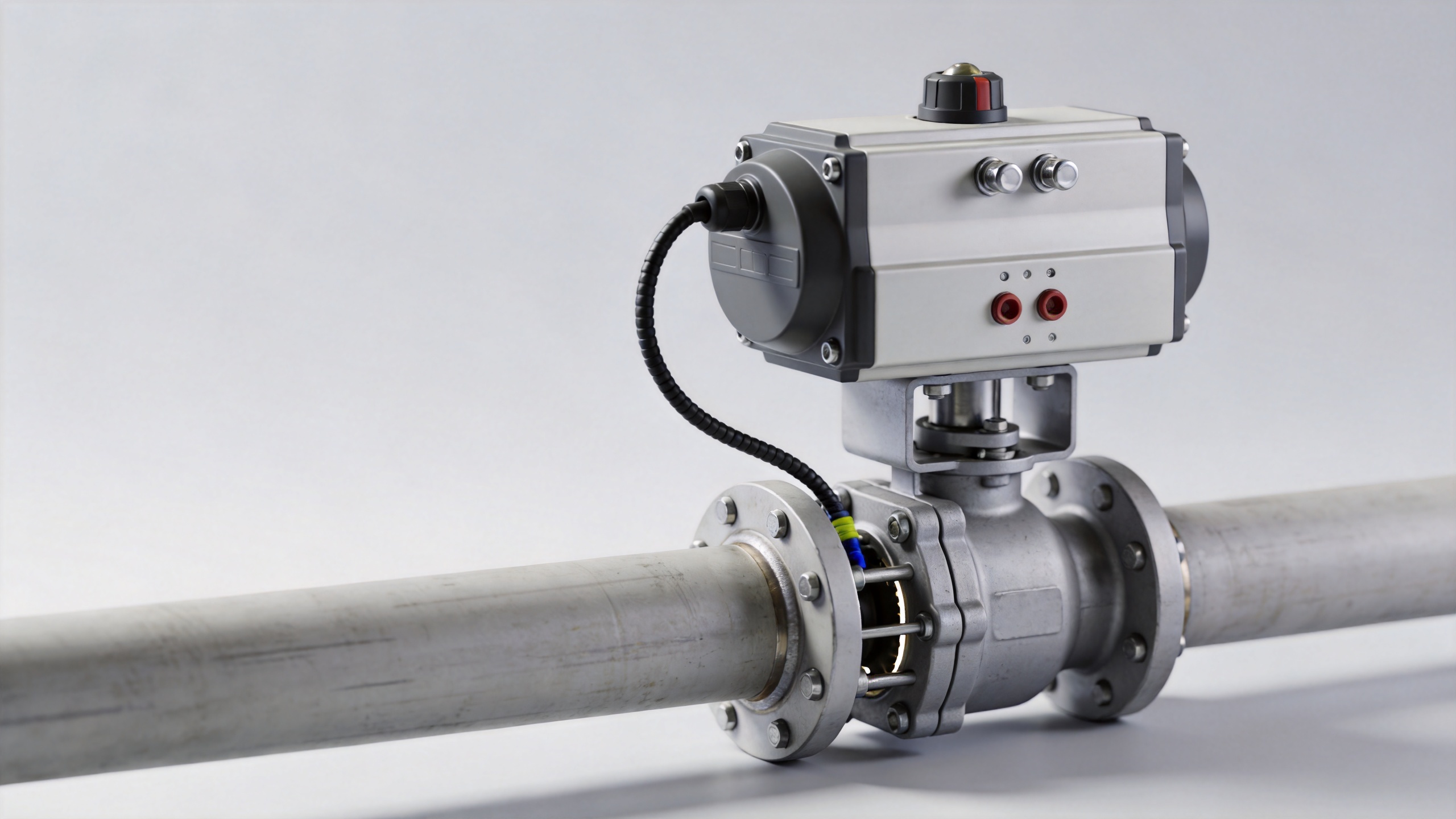
When a 4 Way Directional Control Valve Is the Better Fit
Some motion-control tasks should not be described as ordinary flow regulation. A 4 way directional control valve is used where the system must route fluid to different ports to extend, retract, reverse, or otherwise control an actuator. That is a different duty from simply using an electric control valve to regulate a process stream. For pneumatic or hydraulic motion systems, identify the actuator type, required porting, neutral position, pressure source, and fail behavior before choosing a directional arrangement.
Put differently, do not force a directional-control problem into a modulating process-valve specification. A 4 way directional control valve may be appropriate for cylinder movement, while an electric control valve may be appropriate for controlling a fluid process. The two can exist in the same plant, but they answer different control questions.
How an Air Flow Regulator Valve Changes the Decision
An air flow regulator valve deserves separate consideration when the objective is to control pneumatic flow, such as actuator speed or air delivery. It may be part of a pneumatic circuit rather than a substitute for an electric control valve in a liquid or thermal process. Confirm whether the requirement is air-flow adjustment, directional switching, process-flow regulation, or a combination of these duties. Naming the actual duty prevents a common mistake: comparing products with different functions as though they were interchangeable.
A Practical Deployment Checklist
Before finalizing an electric control valve location, use a short confirmation list:
- What medium will pass through the valve, including changes in temperature, solids, or chemical condition?
- Is the duty on/off, modulating, or directional control?
- What pressure, differential pressure, flow range, and required shutoff behavior apply at the installation point?
- Which valve body, sealing materials, connection, and flow characteristic suit those conditions?
- What electrical power, control signal, position feedback, and fail-state logic are available?
- How often will the electric control valve move, and is there adequate clearance for installation and maintenance?
- Does the project need a relevant industrial-process control-valve standard or a customer specification to be checked before release?
Choose the Deployment Point by System Fit
The right deployment point for an electric control valve is where controlled valve movement supports a defined process outcome: sequencing a utility, regulating a thermal loop, managing a tank, automating a skid, or reducing routine manual access. A reliable result comes from matching the duty to the valve and actuator, then verifying the operating conditions and maintenance reality. If any key condition remains unknown, keep it visible in the specification rather than treating it as already solved. That is a more reliable path to a usable electric control valve installation.
 Hot News





