
 EN
How Does Electric Control Valve Improve Flow Accuracy?
In a process line, flow accuracy is not simply a matter of opening a valve to a stated percentage. It is the ability to produce a stable, repeatable process response when the controller asks for a change. An Electric control valve can improve that response by pairing a controllable valve body with an electric actuator, travel feedback, and a properly configured control loop. For engineers troubleshooting oscillation, overshoot, or poor low-flow control, the useful question is not “Is the valve electric?” but “Can the complete valve assembly translate a demand signal into the intended flow under real differential-pressure conditions?”
This distinction matters in water treatment, chemical handling, HVAC, and other automated systems. A well-selected Electric control valve provides a repeatable mechanical action; it does not erase a poor process design. Sizing, valve authority, installed characteristic, sensor quality, and controller tuning still determine whether the measured flow becomes more accurate.
What “flow accuracy” means in a control loop
Flow control has several layers. A supervisory controller compares the measured process value with a setpoint and sends a command. The Electric control valve converts that command into stem or shaft movement. The valve trim then changes resistance to flow, while the process and flowmeter reveal the final outcome. Position accuracy is therefore necessary but not identical to flow accuracy. A valve may reach 50% travel precisely, yet deliver an unexpected flow if the pressure drop changes or the valve was selected with excessive capacity.
When reviewing a proposed Electric control valve, separate these two questions:
- Will the actuator move the valve to the commanded position reliably?
- Will that position create a predictable change in process flow across the expected operating envelope?
The first is mainly a motion-control problem. The second also involves fluid dynamics and sizing. IEC 60534-2-4 addresses inherent flow characteristics and inherent rangeability, which helps explain why travel-to-flow behavior must be evaluated rather than assumed.
How electric actuation supports repeatable movement
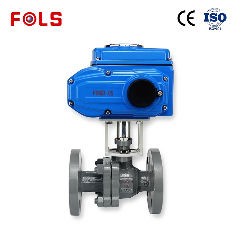
An Electric control valve uses an electric actuator to position a rotary or linear valve. Depending on the assembly, the actuator may receive an on/off, floating, analog, or digital command. Modulating applications need enough resolution, torque or thrust, and speed for the process. If the actuator is too slow, too coarse, or near its torque limit, the loop may lag, hunt, or stop short of the desired position.
Feedback makes the assembly more useful for accuracy-sensitive duty. A travel transmitter or integrated position feedback lets the control system compare the command with actual movement. That feedback can reveal a stuck stem, backlash, inadequate torque, or a mismatch between configured stroke and real stroke. In practice, a feedback-equipped Electric control valve allows commissioning teams to validate motion instead of inferring it from the output signal alone.
For applications requiring pressure management upstream or downstream, an electronic back pressure regulator may be considered as part of the broader control strategy. It is not interchangeable with an Electric control valve: the appropriate device depends on whether the controlled variable is flow, pressure, or a coordinated combination of both.
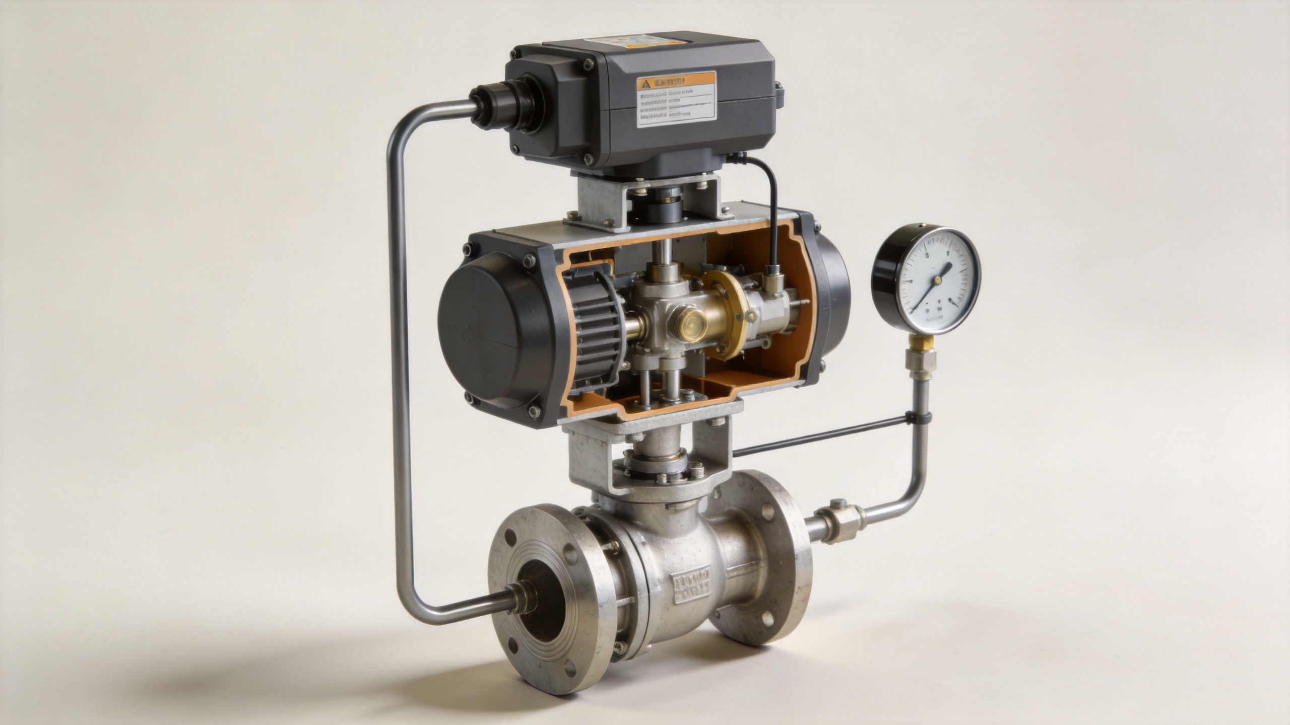
Valve authority and sizing determine whether travel produces useful flow changes
A precise actuator cannot compensate for a valve body selected far outside the process requirement. An oversized Electric control valve can move through small travel increments that cause disproportionately large flow changes, especially near the closed end. This reduces usable resolution and can make the loop appear unstable. Conversely, an undersized valve may spend too much time near full travel, limiting achievable flow and control margin.
Valve authority describes how much of the relevant system pressure drop occurs across the valve. When authority is weak, changes in the rest of the system can dominate the installed characteristic. A correctly chosen Electric control valve should be evaluated at minimum, normal, and maximum flow, with expected inlet and outlet pressures—not just at one nominal design point.
Use the manufacturer’s documented flow coefficient, characteristic, leakage class, torque data, and allowable differential pressure for final selection. Avoid treating a generic Cv, travel percentage, or published rangeability figure as an assured site result. One widely cited practical guideline is to avoid operating permanently at extreme low travel; however, the acceptable range is application-specific and should be confirmed against the selected valve and process model.
Choose a characteristic that works after installation
Linear, equal-percentage, and quick-opening characteristics describe the relationship between valve travel and flow capacity under defined conditions. In a real plant, piping losses, pumps, vessels, and changing differential pressure alter the installed response. The aim is not to choose a characteristic by name alone, but to select an Electric control valve whose installed behavior gives the controller a manageable, gradual response in the operating region.
Equal-percentage trim can be useful where the valve’s pressure drop falls as system flow rises, while linear behavior can be suitable when the pressure conditions are comparatively stable. These are engineering tendencies rather than universal rules. Modeling the operating points is more defensible than relying on a label.
Commission the Electric control valve as a complete loop
Commissioning converts component capability into repeatable performance. Before placing an Electric control valve in automatic service, verify its action, stroke limits, travel direction, fail behavior where applicable, and feedback scaling. Confirm that the control output moves the valve in the expected direction and that the displayed travel agrees with physical travel.
- Check wiring, signal type, stroke time, torque or thrust, and mechanical alignment.
- Calibrate or verify the travel-feedback signal and confirm end stops without forcing the valve.
- Review the flowmeter location and signal quality; noisy or poorly installed measurement can look like valve error.
- Trend command, actual travel, flow, and relevant pressures during controlled step tests.
- Tune the controller after the mechanical and measurement checks, rather than using tuning to mask stiction or sizing problems.
This approach also separates a valve issue from a process issue. For example, a flow loop that improves when the Electric control valve is in manual but oscillates in automatic may require a review of controller settings, measurement filtering, or valve authority—not merely actuator replacement.
Where the auxiliary devices fit
Some hydraulic systems use a hydraulic motor control valve to manage motor speed, direction, or load-related behavior. Its selection criteria may include hydraulic circuit pressure, spool configuration, and motor dynamics. That is a different application from a process-flow Electric control valve, although both require engineers to match the control element to the controlled variable and pressure conditions.
Likewise, an electronic back pressure regulator is often selected when a process needs a controlled upstream pressure. It can complement an Electric control valve in a multi-variable system, but placing both devices in series without a clear control strategy can create interaction and oscillation. Define loop ownership, sensor locations, and setpoint priorities before implementation.
A practical specification checklist
To improve flow accuracy, specify the Electric control valve as an assembly rather than a catalog item. Provide the fluid, temperature, minimum/normal/maximum flow, inlet and outlet pressures, allowable pressure drop, pipe size, control signal, required action, cycle expectations, materials, and environmental conditions. Then request calculations and data that show how the selected trim and actuator perform at each operating point.
Finally, verify the result after installation. Trending setpoint, measured flow, valve command, actual travel, and pressure differential makes it possible to see whether the Electric control valve is delivering useful authority and repeatable movement. That evidence-based process is the most reliable route to tighter flow control.
 Hot News





