
 EN
What Makes Pneumatic Control Valve Ideal For Plants?
A pneumatic control valve can be an excellent fit for a plant when the process needs repeatable automatic regulation and the site can provide clean, reliable instrument air. From an industrial valve application engineer’s viewpoint, the useful question is not whether pneumatic actuation is universally better. It is whether the medium, pressure, temperature, control duty, shutdown philosophy, and maintenance practice make an air-operated valve the sensible choice.
That distinction matters. A control valve regulates a process variable such as flow, pressure, level, or temperature; a directional pneumatic valve manages the air path to equipment. A properly selected pneumatic control valve combines a process valve body with an actuator, and often a positioner, so a plant control system can command a stable valve position instead of relying on manual adjustment.
Why plants often choose pneumatic actuation
Fast response, mechanical simplicity, and a configurable failure action are the main reasons plants consider pneumatic actuation. Compressed air supplies the force that moves the actuator, while a positioner compares the requested signal with actual stem or shaft travel and makes corrections. This arrangement can suit continuous modulating service as well as on/off duty, provided the valve body, trim, actuator torque or thrust, and air supply are matched to the application.
One practical advantage is that a spring-return actuator can be arranged to move toward a defined position when air is lost. Depending on the process hazard review, that position may be fail closed, fail open, or another deliberately specified response. It is not a generic safety promise: a fail-closed fuel line and a fail-open cooling-water bypass protect very different process objectives. The required safe state has to be decided before the actuator action is specified.
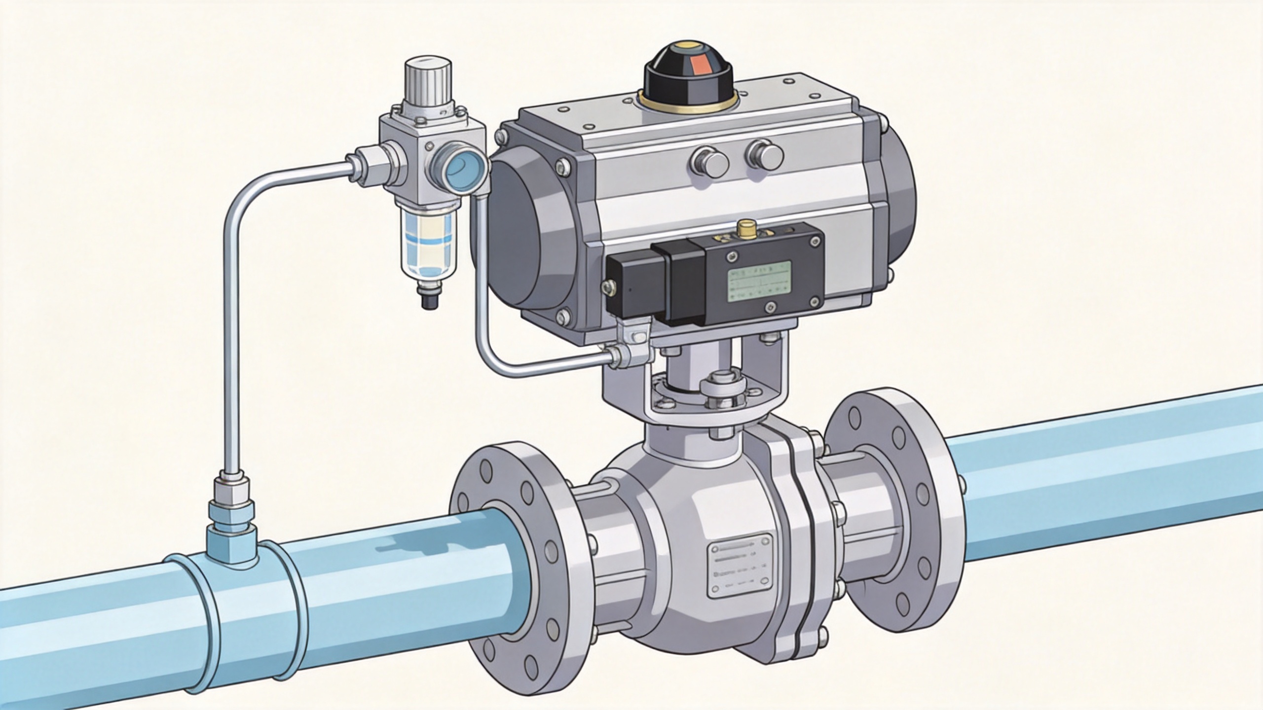
What makes a pneumatic control valve a good plant fit
1. The plant has dependable instrument air
Pneumatic hardware is well suited where instrument air pressure, dryness, cleanliness, and capacity are actively managed. Moisture, oil carryover, particles, undersized tubing, or a shared air header with unstable demand can reduce actuator force and positioner performance. Before selecting a pneumatic control valve, confirm the available air pressure at the actuator during peak demand, the air-quality specification, filter and regulator arrangement, and what happens if the header pressure drops.
2. The process needs a clear failure position
Plants commonly favor a pneumatic control valve when a spring-return mechanism provides a simple way to define the response to loss of air or signal. The engineering team should write the consequence first: does the process become safer when flow stops, continues, bypasses, vents, or holds? Then confirm the valve action, spring direction, and any solenoid or volume-tank logic. Do not infer fail action from the valve name alone; it must be checked against the piping-and-instrument diagram and the actual process scenario.
3. The service requires frequent, repeatable positioning
For throttling loops, repeatability matters more than a quick open-and-close demonstration. A positioner helps the actuator overcome changing packing friction, pressure forces, and travel effects while following the control signal. This can make pneumatic control practical for applications where the process control loop makes continual small corrections. Stable control still depends on correct sizing and tuning: an oversized valve can make fine regulation difficult, while an undersized valve may restrict the required operating range.
4. The valve is sized for the real operating envelope
Valve sizing should use normal, minimum, and maximum operating conditions rather than one nominal flow value. For liquid, gas, or steam service, engineers typically calculate the required flow coefficient and check pressure drop, flashing, cavitation, noise, choked flow, and outlet conditions as applicable. ANSI/ISA-75.01.01 and IEC 60534-2-1 provide a recognized framework for control-valve sizing equations. Using that framework does not choose the product for you; it disciplines the data that must be verified.
Ask for the medium composition, inlet and outlet pressure, temperature range, required flow range, line size, shutoff requirement, and allowable leakage class. Also confirm whether the actuator has adequate thrust or torque at the worst differential pressure. A pneumatic control valve that looks appropriate at nominal conditions may not close securely or modulate accurately at the most demanding condition.
Where the auxiliary valve topics fit
A waste pipe non return valve and a pneumatic control valve solve different problems, but they may appear in the same wastewater or utility installation. The non-return valve is primarily intended to prevent reverse flow. The pneumatic control valve is selected to regulate a process condition. If a plant needs both functions, treat them as separate design checks: confirm backflow protection, then confirm that the modulating valve can handle the operating medium, solids risk, pressure differential, and maintenance access.
Likewise, a 4 inch check valve for sewer should not be assumed to be a substitute for a control valve simply because both sit in a pipeline. Pipe size, sewage characteristics, head conditions, sealing behavior, and reverse-flow risk guide check-valve selection. Modulation needs, fail action, actuator compatibility, and signal control guide pneumatic control-valve selection. Separating those duties early avoids a specification that is neither a reliable check valve nor an effective regulating valve.
A practical selection sequence for plant teams
- Define the controlled variable and operating window. State whether the loop controls flow, pressure, level, or temperature, then document normal and upset conditions.
- Establish the required safe response. Link fail-open, fail-closed, or another response to the process safety review, not to a default actuator convention.
- Choose the valve body and trim for the medium. Consider corrosion, erosion, solids, temperature, pressure drop, shutoff expectations, and maintainability.
- Size the valve and actuator together. Check the flow calculation as well as available actuator force or torque at the highest differential pressure.
- Validate the instrument-air system. Confirm supply pressure, quality, capacity, tubing, filtration, regulation, and response during an air-loss event.
- Specify feedback and maintenance needs. Decide whether a positioner, limit switches, solenoid valve, air set, manual override, or diagnostic capability is needed for the control strategy.
When another approach may be better
Pneumatic actuation is not automatically the right answer. If the plant cannot maintain suitable compressed air, an electric actuator may be easier to support. If the required duty is infrequent and simple, elaborate position control may add unnecessary complexity. If the process demands a specific holding behavior after utility loss, the actuator and auxiliary system need a closer review than a basic spring-return arrangement. The right choice follows the operating conditions, not a preference for one power source.
Conclusion
A pneumatic control valve is ideal for plants when it supports the actual control task, works with the available instrument-air infrastructure, provides the needed failure response, and is sized across the real process envelope. Start with the process data and shutdown objective, then verify the valve body, actuator, positioner, and air system as one assembly. That approach produces a more defensible specification than selecting by valve label or actuator type alone.
 Hot News





