
 EN
What Are The Uses Of 3-Way Ball Valve In Piping?
In a piping system, a 3-Way Ball Valve is used when one valve must manage more than a simple open-or-close duty. Its three ports let a process route a fluid from one line to another, combine two streams, send flow around equipment, or isolate one branch while another remains in service. The right use depends on the ball’s port pattern and the piping flow diagram—not merely on the number of ports.
From a process-control viewpoint, the useful question is: “Which ports must communicate in each operating position?” Answer that before selecting the valve body, seats, handle, or actuator. It prevents a common installation problem: a valve that physically fits the line but cannot produce the intended flow path.
How a 3-Way Ball Valve Routes Flow
A 3-Way Ball Valve has a drilled passage through its rotating ball. Turning the stem changes which ports are connected. Instead of installing two separate two-way valves and coordinating their positions, one multi-port valve can perform a defined switching, diverting, or mixing function.
The port labels on a drawing are often called A, B, and common port AB, although the actual designation varies by manufacturer. Do not rely on handle orientation alone to determine the flow direction. Review the manufacturer’s flow chart for every valve position, especially where an actuator will move the valve automatically.
L-Port Uses: Switching Between Two Paths
An l port valve has an L-shaped bore. In a typical arrangement, it connects the common port to either one of two side ports. It is therefore well suited to selection and changeover duties rather than simultaneous flow to both branches.
- Duty/standby equipment changeover: Route a liquid supply to one filter, pump, or treatment skid while the other path is isolated for service.
- Source selection: Choose between two compatible feed lines that supply the same downstream process.
- Sampling or flushing paths: Switch a line between normal service and a defined flush or drain connection, when the process design permits it.
- Bypass selection: Send flow through equipment in normal operation or around it during maintenance, provided the bypass scheme is reviewed for pressure, temperature, and safety implications.
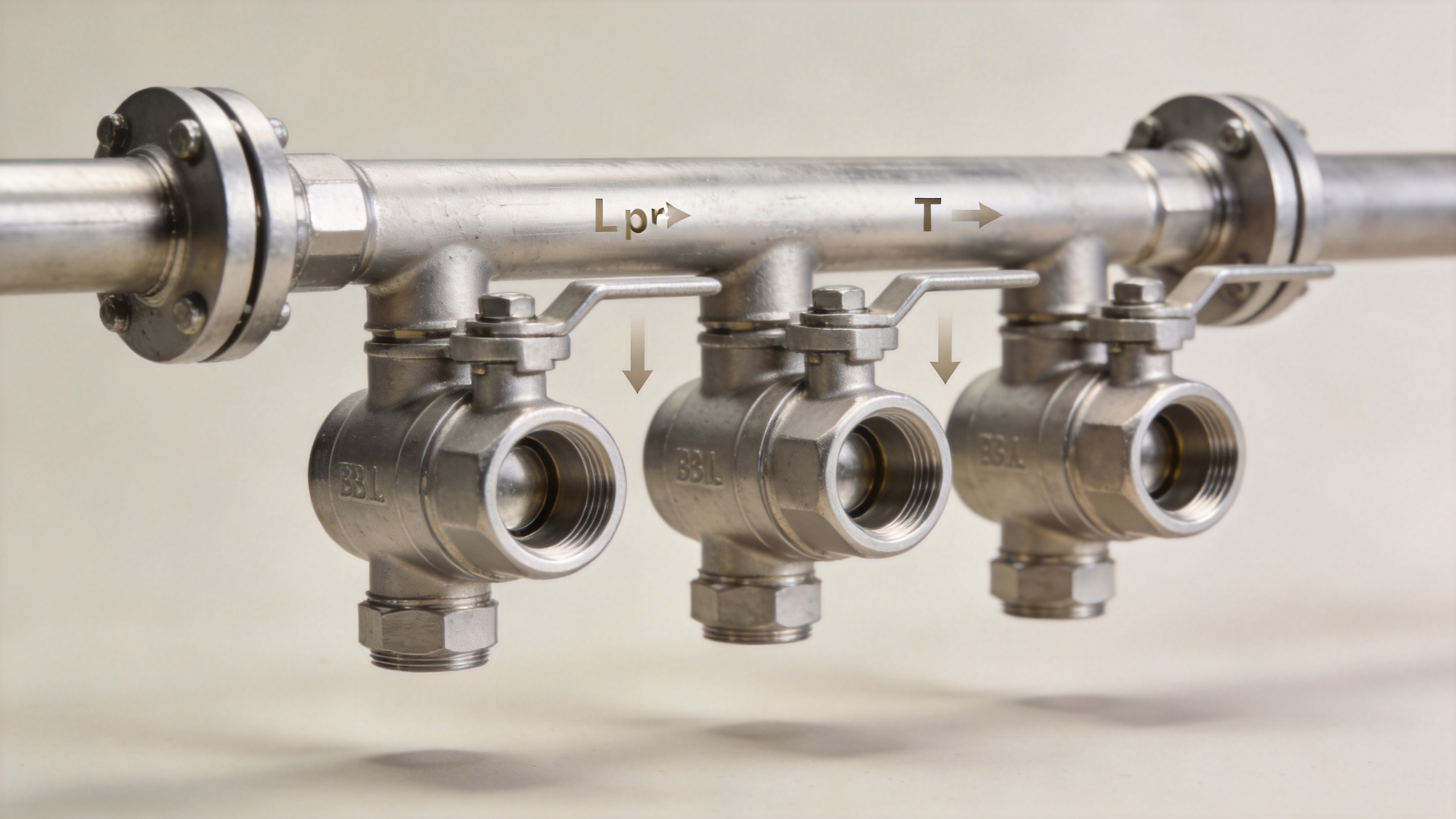
The important limitation is that an L pattern does not automatically create a mixing duty. Its strength is positive path selection. Depending on the ball design, a rotation may also create a closed position; that detail must be confirmed in the valve documentation.
T-Port Uses: Diverting, Mixing, and Multi-Path Routing
A T-port ball contains a T-shaped passage. It can offer more routing combinations than an L pattern, making it useful where a process needs to divert one stream, combine compatible streams, or connect multiple ports in a specified position. The available combinations still vary by ball drilling and stop arrangement.
Diverting one inlet to alternative destinations
For example, a process may send a fluid to production during normal operation and to a recovery, recirculation, or alternate treatment line during another operating state. A T-port 3-Way Ball Valve can simplify this routing when the desired positions are clearly defined.
Mixing compatible streams
Where two compatible streams must enter one outlet, a T-port arrangement may be used as part of the piping scheme. This is common in utility and process layouts that need controlled temperature, concentration, or flow routing. A ball valve is a routing device, however; if the duty requires precise modulation, assess whether the control strategy, actuator, characterization, and downstream measurement are appropriate for that level of control.
Recirculation and equipment protection arrangements
Some systems use a multi-port valve to move between process flow and a recirculation loop. The piping designer must confirm that each valve position protects the equipment and does not trap liquid, create an unintended dead end, or place an unsuitable pressure differential across the valve.
Where These Valves Appear in Piping Systems
The practical uses of a 3-Way Ball Valve span water handling, wastewater treatment, chemical processing, oil and fuel handling, HVAC utilities, and general industrial automation. The common thread is not the industry name; it is the need to control a defined set of flow paths with a compact quarter-turn valve.
| Process need | Typical valve function | Key design check |
|---|---|---|
| Two supply lines to one process line | L-port source selection | Confirm isolation requirements and compatibility of both fluids. |
| One supply line to two destinations | L- or T-port diversion | Verify that the selected port pattern gives the intended outlet in each position. |
| Normal path and service bypass | Path changeover | Check pressure drop, isolation sequence, and maintenance procedure. |
| Mixing or recirculation layout | T-port multi-path routing | Review the flow diagram, media compatibility, and control accuracy required. |
Manual Lever or Pneumatic Actuation?
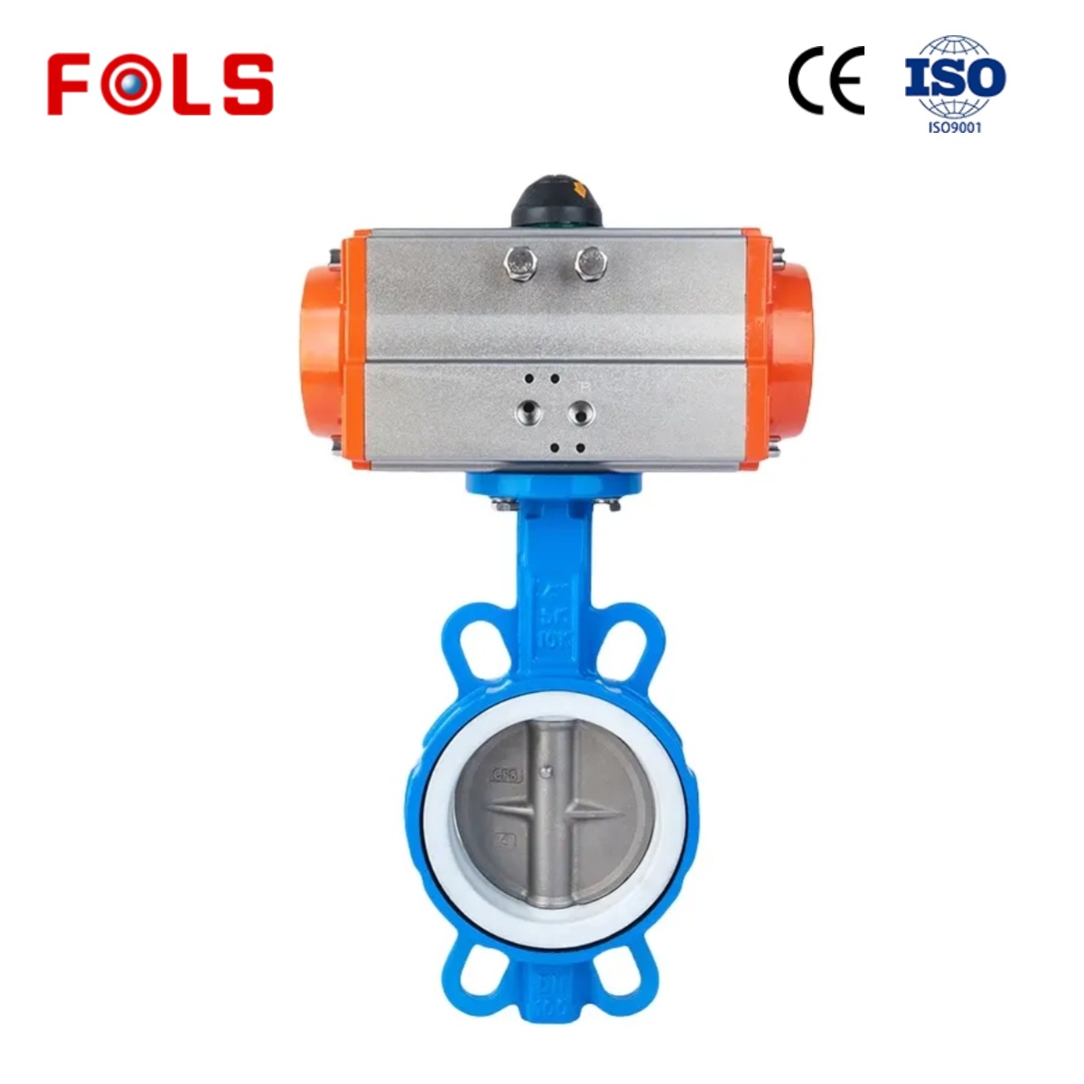
A manual handle is practical where an operator can safely reach the valve and the switching frequency is low. The phrase pneumatic lever valve is sometimes used loosely in purchasing discussions, but the key distinction is between a manually operated lever valve and a pneumatically actuated ball valve. A pneumatic actuator replaces the manual turning effort and can be paired with position feedback, solenoid control, or a defined fail position.
Choose pneumatic actuation when the valve must change position remotely, repeatedly, or as part of an interlocked sequence. Then document whether loss of air should move the valve toward the process-safe flow path. That decision should come from the P&ID and hazard review, not from a generic preference for fail-open or fail-closed hardware.
Selection Checklist Before Ordering
- Draw the required flow paths. List the ports that must communicate in every operating and fail position.
- Select L or T geometry from the flow chart. A port name alone is not enough; drilling and stop positions matter.
- Check the medium. Verify body, ball, seal, and seat materials for the fluid, solids content, cleaning method, and temperature range.
- Check operating limits. Match the pressure-temperature rating, pressure differential, and end connection to the actual line conditions.
- Define actuation. Decide whether a lever, pneumatic actuator, or electric actuator fits access, cycle frequency, control signal, and required fail action.
- Plan commissioning. Stroke the valve through each position, confirm port-to-port communication, and label the handle or actuator positions for the operating team.
Final Takeaway
The main uses of a 3-Way Ball Valve in piping are switching, diverting, mixing, bypassing, and routing flow around equipment. An L-port design is commonly chosen for selecting between two paths, while a T-port design supports broader multi-path routing when its flow diagram matches the duty. Start with the required piping connections in each position, then verify materials, ratings, and actuation. That sequence produces a valve choice that supports the process instead of complicating it.
 Hot News





