
 EN
Where Should Flanged Butterfly Valve Be Installed?
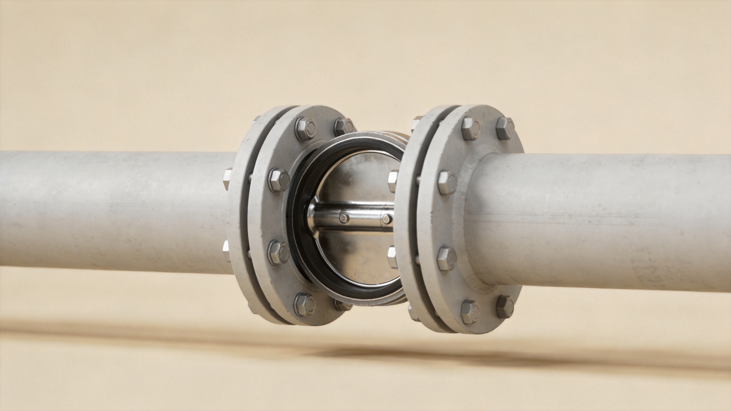
A Flanged Butterfly Valve is usually installed where a pipeline needs a bolted, face-to-face connection that is easy to inspect, support, and service. The appropriate location is not simply “any flanged pipe.” It is a position where the valve body, disc, actuator, pipe flanges, and maintenance team all have the room and operating conditions they need. From a process-engineering perspective, the installation decision should start with the line duty, then move to geometry, access, and verification against the selected manufacturer’s documentation.
This guide explains where a Flanged Butterfly Valve commonly fits in water, wastewater, industrial utility, chemical, and larger-diameter piping systems. It also highlights locations where a different connection or valve type may be more practical. The goal is a usable screening framework, not a substitute for the pressure-temperature rating, face-to-face dimensions, materials, and installation instructions supplied for a specific valve.
Start with the purpose of the line
A Flanged Butterfly Valve is a strong candidate for on-off isolation, throttling within its intended range, or automated flow control in pipelines that benefit from a rigid bolted connection. It is often considered on main headers, pump discharge lines, treatment-process sections, tank connections, and branch lines where disassembly will eventually matter. The flange connection can be especially useful when pipe sizes, valve weight, vibration, or maintenance expectations make a more robust connection desirable.
The medium still controls the decision. Clean water, cooling water, air, wastewater, slurry-bearing streams, chemicals, and oil-related services can place very different demands on the disc, seat, stem, body, and actuator. A Flanged Butterfly Valve should therefore be specified around the actual medium, temperature, pressure, solids content, cycling frequency, and required shutoff—not around the connection style alone.
Common installation locations
1. Main water and wastewater pipelines
Large water distribution, raw-water intake, irrigation, and wastewater treatment lines are common homes for a Flanged Butterfly Valve. In these systems, operators often need dependable isolation at pump stations, basin inlets and outlets, filter lines, or treatment skids. A flanged body can be easier to remove for inspection than a permanently joined section, provided the pipework includes adequate support and safe access for lifting and bolting.
Place the valve where the disc can open without striking adjacent pipe features, reducers, strainers, or instruments. Leave enough space for an operator to reach the hand lever, gearbox, pneumatic actuator, or electric actuator. In wastewater duty, also consider whether deposits, rags, solids, or sediment may affect disc travel or prevent reliable seating. These are configuration questions that should be confirmed with the valve supplier for the intended service.
2. Pump discharge and equipment isolation points
A Flanged Butterfly Valve is frequently installed downstream of pumps, vessels, heat exchangers, filters, or other equipment that may need to be isolated. The location should enable equipment maintenance without forcing personnel to dismantle unrelated piping. It should also allow safe handling of the valve during future removal. Do not treat the valve as a pipe support: independently support heavy valves, actuators, and nearby pipe loads so the flange faces remain aligned.
Where a pump discharge line may see pressure surges or frequent starts and stops, review the complete hydraulic duty before selecting a Flanged Butterfly Valve. Valve closure speed, actuator control, line velocity, and surge analysis can affect the preferred installation arrangement. A check valve may also be required by the system design; one component does not automatically replace the function of another.
3. Process and utility headers that need controlled isolation
In industrial plants, a Flanged Butterfly Valve may be placed on cooling-water loops, utility-air networks, process-water headers, fire-water arrangements where the approved design permits it, and other services requiring a clear isolation point. The flanged interface helps when the project specification calls for defined flange drilling, pressure class, or inspection practices. Standards such as API 609 and applicable ASME or EN flange requirements can guide purchasing and compatibility checks, but they do not confirm that a particular installed assembly is suitable. Verify the actual valve marking and project specification.
Keep the valve away from locations that make access difficult: directly beneath leaking equipment, behind structural steel, too close to an elbow that restricts handle travel, or inside an enclosure with no route for actuator removal. A technically compatible Flanged Butterfly Valve becomes a poor installation when routine operation or emergency isolation requires unsafe access.
4. Lines that require frequent inspection or replacement
Choose a Flanged Butterfly Valve where future serviceability has real value. Chemical transfer systems, abrasive or dirty services, and installations with planned inspection intervals may justify a bolted design because technicians can remove the valve after isolating, draining, depressurizing, and supporting the line. This does not mean every flanged location is automatically service-friendly. Plan clearance for bolts, flange spread, lifting equipment, and the route needed to remove the valve.
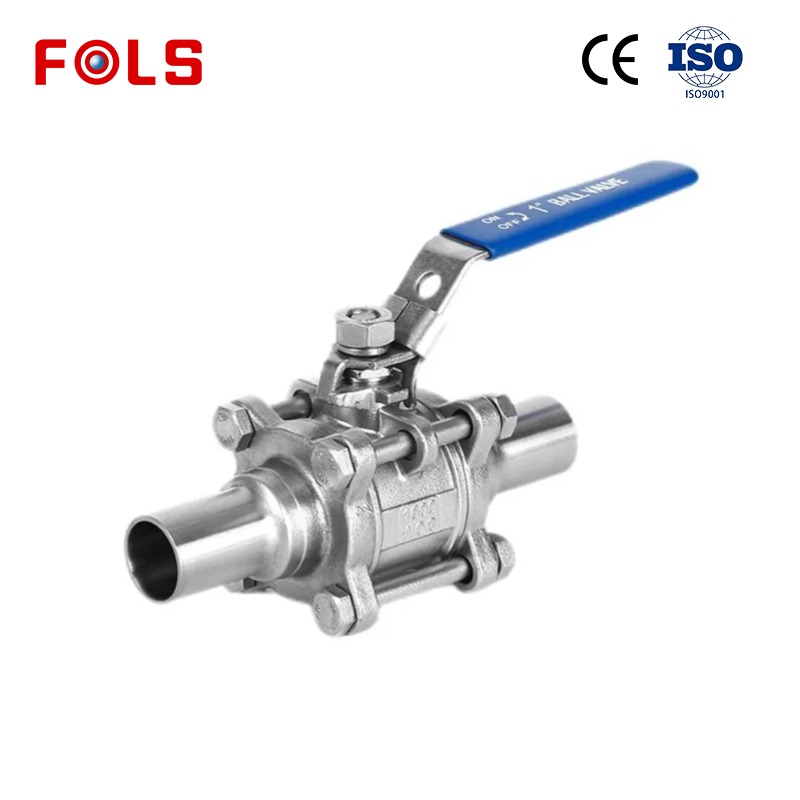
For smaller ancillary lines, a 3 inch ball valve stainless steel design may be a more appropriate point-isolation option when the service, bore requirement, material compatibility, and control purpose support a ball valve. Likewise, a pvc true union ball valve can be useful in compatible low-pressure plastic piping where quick removal and material compatibility are the governing needs. These examples are not replacements for a Flanged Butterfly Valve; they illustrate why the line size, medium, connection system, and maintenance plan should be evaluated together.
Where a flanged butterfly valve needs extra caution
A Flanged Butterfly Valve may be less suitable when the system needs very fine control near the closed position, exceptionally tight shutoff beyond the selected valve’s rated capability, a full unobstructed bore, or a design built around threaded, welded, grooved, or plastic solvent-welded connections. High-pressure, high-temperature, corrosive, oxygen, sanitary, or hazardous service demands a detailed engineering review. Seat material, disc alloy, stem sealing, fire-safe requirements, fugitive-emissions expectations, and pressure-temperature limits are not details to infer from the words “butterfly valve.”
Installation geometry deserves the same caution. Do not force misaligned pipe flanges together with the bolts; that can load the body and seat. Confirm the mating flange standard, nominal size, bolt pattern, gasket arrangement, and available disc clearance before tightening. Use a controlled bolting sequence according to the project procedure and valve documentation. Before commissioning, cycle the Flanged Butterfly Valve through its intended travel with the line in a safe condition and confirm that the actuator, position indication, and access route work as designed.
A practical placement checklist
- Does the line duty match the materials, pressure-temperature rating, and shutoff performance of the Flanged Butterfly Valve?
- Are the mating flanges centered, parallel, correctly drilled, and supported without using the valve as a structural member?
- Can the disc travel freely, with no interference from pipe internals, reducers, instruments, or nearby equipment?
- Is there room to operate, inspect, remove, and maintain the handle, gearbox, or actuator?
- Has the design addressed isolation, draining, depressurization, lifting, and any needed check-valve or surge-control functions?
- Have the selected valve’s drawings and installation instructions been checked before field work begins?
Conclusion
Install a Flanged Butterfly Valve where the process needs a bolted isolation or control point and the layout can provide alignment, independent support, disc clearance, and safe maintenance access. Main water and wastewater lines, pump discharge isolation points, process headers, and serviceable equipment connections are often suitable locations. The final answer depends on the actual operating conditions and the specific valve documents. By reviewing the full system rather than the valve body alone, project teams can select an installation point that remains practical throughout commissioning and maintenance.

 Hot News





