
 EN
Where Should Check Valve Be Installed In Networks?
A Check Valve belongs where reverse flow would damage equipment, drain a line, disturb another branch, or create an unwanted process path. The idea is simple, but the right location depends on the network rather than the valve alone. From a piping-application engineer’s viewpoint, start with the fluid path, pressure changes, elevation, shutdown behavior, and service access. Then choose the Check Valve location that supports those conditions.
Do not begin with the valve body. Begin with the question: when flow stops or reverses, what must remain protected? In drainage, water treatment, chemical transfer, and automated process lines, the answer can be a pump, a parallel line, a storage vessel, or an instrument loop. The following placement guide gives a practical starting point, but the final arrangement still needs the applicable piping design, valve instructions, and project requirements.
Start With Flow Direction and the Reverse-Flow Path
Every Check Valve should be installed with its body arrow aligned to normal process flow. Before selecting a location, trace the route that fluid would take after a pump stops, a pressure source falls, or a higher-pressure branch becomes active. The Check Valve should interrupt that route while remaining accessible for inspection and replacement.
That broader view matters because a fitting can work correctly on its own yet perform poorly in a turbulent or poorly supported line. Confirm the medium, operating pressure and temperature, pipe orientation, expected flow range, solids content, and whether closure speed matters. A location that suits clean, steady water may need revision for slurry, pulsating flow, gas, or a corrosive liquid.
Place a Check Valve on Each Pump Discharge Line
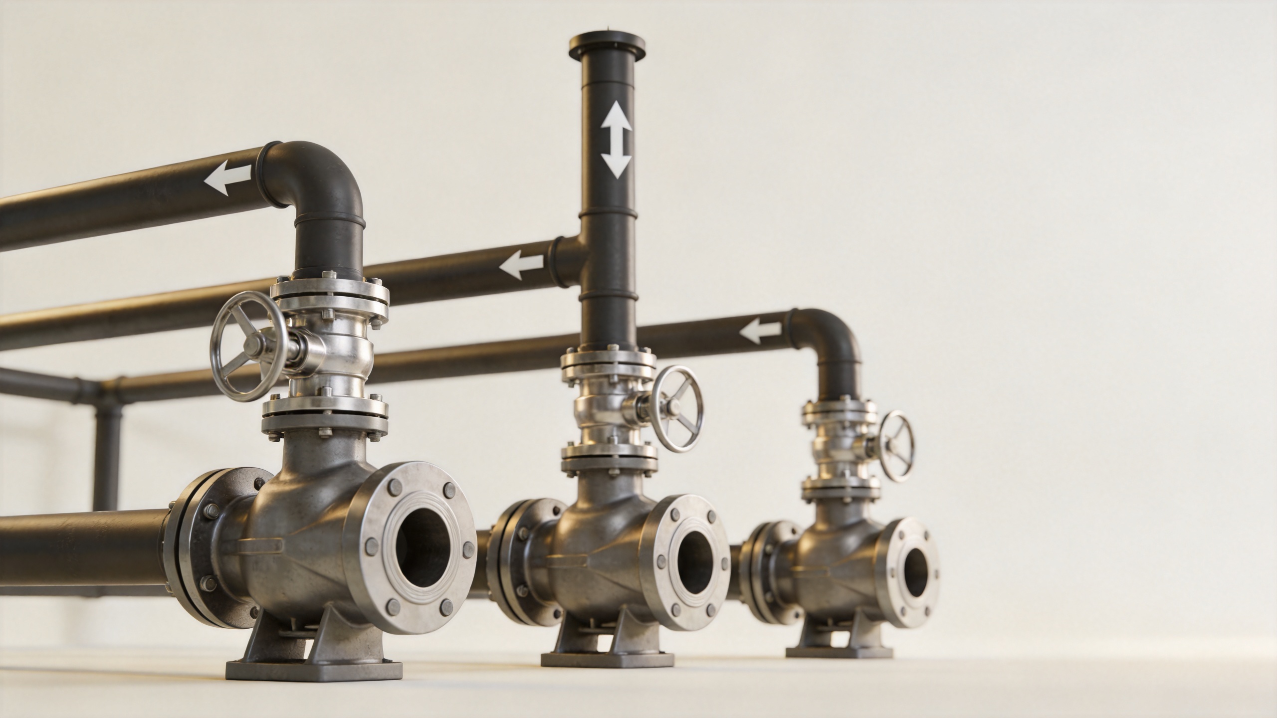
The most common location for a Check Valve is on the discharge piping of a pump. It is normally positioned so that a stopped pump is isolated from reverse flow coming back from the discharge network. In a parallel-pump arrangement, each pump discharge generally needs its own Check Valve before the lines join. Otherwise, flow from an operating pump can move through an idle pump branch.
Keep the valve close enough to the pump to limit the volume that can reverse through the pump, but do not assume that “as close as possible” is an engineering rule for every layout. A pump outlet, elbow, reducer, or control element can leave a disturbed velocity profile. Review the valve manufacturer’s installation instructions and the hydraulic design for the inlet conditions and straight-run requirements. The selected Check Valve also needs a support arrangement that does not load the pump nozzle.
A shutoff valve is often installed in the discharge train for maintenance isolation. The exact sequence must follow the system design and operating procedure. What matters is that the Check Valve can close against the reverse-flow path it is meant to control; it should not be left on a bypassed or isolated section of pipe.
Protect Branches, Parallel Equipment, and Tank Connections
Install a Check Valve in a branch when flow from the main header could travel backward into that branch during pressure changes. This is common where multiple pumps feed one manifold, where tanks are connected at different pressure levels, or where a standby line must remain isolated until called into service. For a tank outlet, the right Check Valve location depends on whether the concern is backflow into the tank, loss of line inventory, or interaction with another feed source.
At a mixing point, examine all normal and abnormal operating states: one pump running, both pumps stopped, a downstream valve closing, or a bypass open. The placement decision should be based on those states, not merely the normal flow drawing. A Check Valve cannot resolve a process-control conflict on its own, so confirm whether an isolation valve, control valve, relief arrangement, or interlock is also needed.
Vertical Runs Need an Orientation Check
A vertical line deserves special attention because gravity can affect disc or poppet movement and because a tall liquid column can create substantial reverse-flow energy. Some Check Valve designs are intended for horizontal service or vertical upward flow only, while spring-assisted or axial designs may have different permitted orientations. Read the product installation and maintenance instructions rather than applying a generic rule.
For a rising discharge line, locate the Check Valve where it can retain the desired liquid column and protect the equipment below it. For long risers, intermediate valves or a different closure characteristic may be evaluated as part of surge analysis. Avoid presenting a fixed spacing as universal: elevation, pipe size, fluid properties, pump coastdown, and valve closing behavior all change the result.
Choose the Valve Type for the Available Space
A 4 wafer check valve can be a practical option where flange-to-flange space is limited and the piping design calls for a wafer configuration. Its location still needs enough clearance for installation, removal, and the specified flange arrangement. Confirm the disc travel, allowable orientation, pressure class, materials, and any upstream-flow conditioning stated by the manufacturer. A compact 4 wafer check valve does not remove the need to assess turbulence or service access.
For automated networks, keep the roles separate. A Check Valve controls unintended reverse flow automatically; it does not modulate process flow. A smart positioner belongs with an actuated control valve where controlled positioning and feedback are required. If a line includes both functions, put the Check Valve where it protects the reverse-flow path and locate the control assembly where it can regulate the intended process variable. The smart positioner configuration should then be checked against the control-valve and control-system requirements.
Installation Checks Before Commissioning
- Verify the Check Valve arrow against the piping flow direction.
- Confirm that valve type, seat materials, pressure rating, and permitted orientation match the actual service.
- Check inlet and outlet geometry against the valve instructions, especially near elbows, reducers, pumps, and tees.
- Provide clearance to inspect, remove, or service the Check Valve without dismantling unrelated pipework.
- Review supports so pipe weight and vibration are not transferred into the valve or connected equipment.
- During commissioning, observe the Check Valve through startup and controlled shutdown for noise, chatter, leakage, or an unexpected pressure response.
Use a Location Decision Path
For most networks, the decision path is straightforward: identify the reverse-flow route, place the Check Valve in that route, verify normal-flow direction, assess the local hydraulic conditions, and confirm the valve design for the mounting orientation. Where multiple sources, long vertical runs, hazardous fluids, or rapid pump shutdown are involved, involve the responsible piping and process engineers before installation.
A more useful question is not “Where does any Check Valve go?” but “Which reverse-flow event must this Check Valve control, and what conditions will it face there?” That framing leads to a location that is easier to justify, inspect, and maintain.
 Hot News





