
 EN
What Makes Hydraulic Control Valve Key For Machinery?
On a machine floor, a hydraulic control valve is rarely an isolated part. It is the decision point between available pump flow and useful, repeatable motion. From an automation-control perspective, the valve tells oil where to go, how much pressure the circuit can develop, how quickly an actuator moves, and what happens when a command changes. That is why a hydraulic control valve can affect productivity, energy loss, safety planning, and troubleshooting long after installation.
The useful question is not simply whether a valve fits a port or a catalog category. It is whether its function matches the machine’s motion, load, fluid, control method, and maintenance conditions. A hydraulic control valve that is appropriate for one circuit may be unsuitable for another even when the nominal size looks similar.
A hydraulic control valve turns fluid power into controlled motion
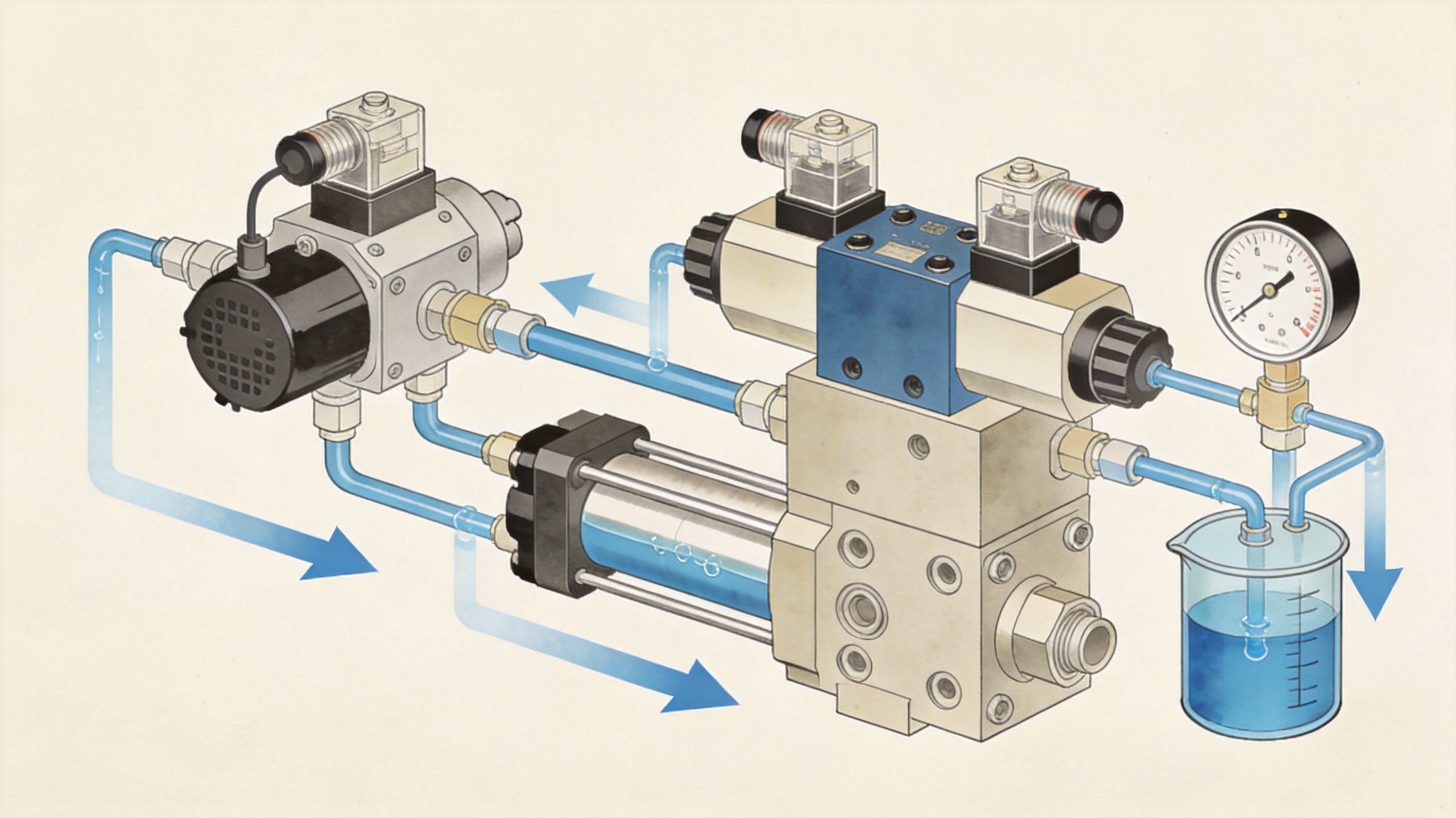
Hydraulic systems create force by moving pressurized fluid, but force alone does not produce a controlled machine cycle. A hydraulic control valve establishes the flow path between the pump, actuator, reservoir, and any related circuit branches. Depending on its design, it can start or stop movement, reverse a cylinder, hold a load, limit pressure, regulate actuator speed, or prioritize one function over another.
For example, a directional hydraulic control valve can route oil to either side of a double-acting cylinder so the rod extends or retracts. A pressure-control device may protect a branch from excessive pressure. A flow-control device can influence travel speed and sequencing. Check functions prevent unwanted reverse flow. These functions often work together, which is why calling every component “a valve” is not enough for specification or fault finding.
In a circuit drawing, the symbol and spool positions matter. ISO 1219 is widely used for fluid-power symbols and diagrams, so reviewing the schematic is a practical way to confirm ports, neutral condition, and intended flow paths before a hydraulic control valve is selected or replaced.
Why the neutral condition changes machine behavior
When a directional valve is not actively shifted, its center or neutral condition may connect, block, or unload particular ports. That detail has consequences. A blocked-center arrangement can hold an actuator position under appropriate system conditions, while an open-center arrangement may provide a different path for pump flow. Neither is automatically better. The correct choice depends on pump type, actuator behavior, load requirements, and the rest of the circuit.
This is a common purchasing blind spot: people compare port count and lever positions but do not confirm what the hydraulic control valve does between commands. On equipment with a fixed-displacement pump, an unsuitable neutral path can contribute to unwanted heat or pressure behavior. On a load-handling function, the circuit may need more than the directional spool alone to maintain safe control. Verify the schematic and duty cycle rather than assuming the replacement will behave like the original.
Valve selection begins with the operating conditions
A practical selection review starts with the machine, not a model number. Gather the following information before comparing a hydraulic control valve:
- Motion and actuator: Is the valve controlling a cylinder, hydraulic motor, clamp, lift, steering function, or several functions?
- Required flow: What flow is needed for the intended actuator speed, and what flow may pass through the valve in each operating mode?
- Pressure and load: What are the normal and maximum system pressures, load changes, shock conditions, and relief strategy?
- Fluid and temperature: What fluid, viscosity range, filtration practice, and temperature range will the system experience?
- Ports and installation: Which port standard, mounting arrangement, hose routing, and service access are required?
- Control method: Will the hydraulic control valve be manual, pilot-operated, electrically actuated, or proportional?
This checklist prevents a familiar mistake: selecting by initial price or body size before flow, pressure, and circuit behavior are defined. It also gives technical teams a clearer basis for comparing hydraulic valve suppliers. A supplier can provide a more useful recommendation when the application data is complete, while an incomplete request tends to produce only a broad catalog match.
Manual, solenoid, and proportional control solve different problems
Manual actuation can be appropriate where an operator directly controls a straightforward function. Pilot-operated and solenoid-actuated arrangements can support remote commands or higher operating forces. A solenoid coil 24vdc is not merely an accessory; its voltage, connector, duty cycle, environmental protection, and available electrical supply must match the valve and machine controls.
For a solenoid-operated hydraulic control valve, confirm whether the coil is intended for continuous energization and whether the controller can supply the required current. Also check the de-energized position. If power is lost, the machine must respond in a way that fits the risk assessment and circuit design. Requirements such as ISO 4413 address general rules and safety considerations for hydraulic systems and their components on machinery, but a project still requires application-specific engineering and local compliance review.
Proportional control may be considered when the machine needs more graduated motion than an on/off spool can provide. It brings additional setup questions, including signal range, ramping, feedback, contamination sensitivity, and commissioning. The hydraulic control valve should therefore be evaluated as part of the control architecture, not as a stand-alone electrical purchase.
Reliability depends on the whole circuit
Even a correctly selected hydraulic control valve can perform poorly if contamination, heat, aeration, incorrect plumbing, or unstable pressure is left unresolved. Sticky spool movement, slow response, pressure spikes, or drift may point to several possible causes. Replacing the valve without checking oil condition, filters, hoses, relief settings, and actuator condition can hide the real problem.
Maintenance planning should include clean handling during installation, confirmation of port identification, torque and sealing practices specified for the product, and a functional test at controlled conditions. Record the symptoms, measured pressures, flow behavior, and command state. That evidence makes it easier to distinguish a valve issue from a pump, cylinder, electrical, or plumbing issue.
How to ask hydraulic valve suppliers better questions
When contacting hydraulic valve suppliers, provide the circuit function, fluid, pressure range, target flow, actuator type, desired neutral condition, port details, environmental exposure, and control voltage. For an electrically actuated option, state whether a solenoid coil 24vdc is required and share connector or wiring constraints. Ask for the product data needed to verify compatibility rather than asking for a universal valve.
It is also sensible to separate confirmed requirements from items still being validated. For example, a team may know its nominal flow but still need to confirm peak flow during simultaneous functions. That distinction avoids treating preliminary assumptions as final specifications and helps keep a hydraulic control valve decision traceable.
Conclusion
A hydraulic control valve is key for machinery because it converts hydraulic energy into intentional, repeatable action. Its value lies in the way it directs, regulates, protects, or holds fluid power within a complete circuit. Start with the machine’s motion and operating conditions, verify the schematic and neutral behavior, match electrical control details where applicable, and review maintenance needs before ordering. That process is more reliable than selecting a valve by appearance, price, or a partial part number alone.
 Hot News





