
 EN
What Is a Globe Valve and How Does It Regulate Flow?
A Globe Valve is a linear-motion valve used to start, stop, or regulate flow in a pipe. Its defining feature is a movable plug or disc that approaches or withdraws from a stationary seat. That movement changes the size of the flow passage, which is why a Globe Valve is commonly considered when a process needs more control than a simple open-or-closed device provides.
From an industrial valve application engineer’s perspective, the useful question is not merely whether a Globe Valve can regulate flow. It is whether the medium, pressure, temperature, required rangeability, shutoff expectation, and operating method suit that valve and its trim. A correct answer depends on the service conditions.
How a Globe Valve Works
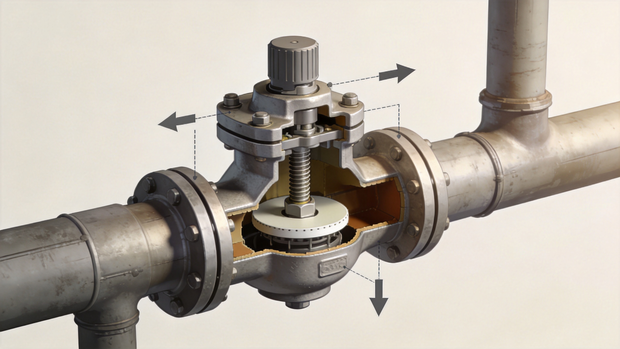
Inside a typical Globe Valve, the body guides fluid through a seat opening. A stem connects the operating mechanism to the plug or disc. Turning a handwheel, or receiving motion from an actuator, moves the stem in a straight line. As the plug lifts away from the seat, the available area for flow increases. As it moves toward the seat, that area becomes smaller and resistance rises. When the seating surfaces meet, the valve closes.
That gradual change in opening is how a Globe Valve regulates flow. The valve does not create flow; it establishes a restriction whose position can be adjusted. The actual result depends on the pressure differential, fluid properties, piping arrangement, and valve sizing. In other words, a partially open Globe Valve is not automatically a precise control solution unless its capacity and operating range fit the application.
Main parts and their roles
- Body and bonnet: contain the pressure boundary and support the internal components.
- Seat: provides the fixed sealing and throttling surface.
- Plug or disc: moves relative to the seat to vary the opening.
- Stem: transfers linear motion from the handwheel or actuator to the plug.
- Packing and gland: help limit leakage around the moving stem, subject to the selected design and service conditions.
A Globe Valve body often makes the flow change direction inside the valve. That geometry supports throttling, but it can also create more pressure loss than a straight-through alternative. Do not first ask which valve is “better”; first write down the medium, pressure drop allowance, and control objective.
Why Globe Valves Are Used for Flow Regulation
The plug-and-seat relationship gives a Globe Valve a practical advantage in throttling service: operators can hold the closure element at intermediate positions instead of treating the valve as only fully open or fully closed. The shape of the plug and the trim design influence how flow changes as stem travel changes. Linear, equal-percentage, and quick-opening characteristics are common descriptions in control-valve work, but the selected characteristic must be evaluated with the installed system rather than in isolation.
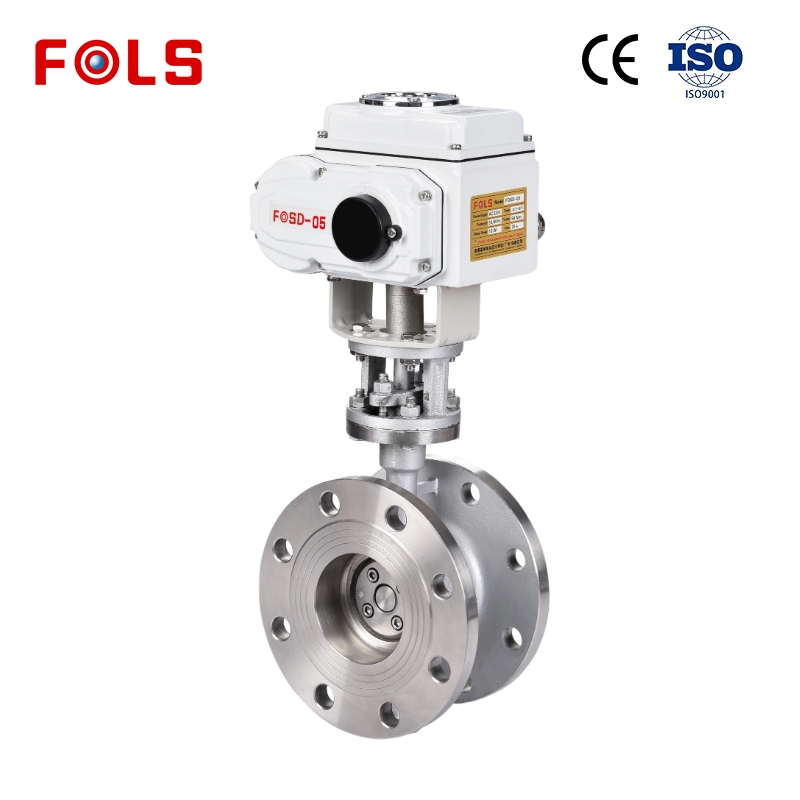
For automated service, a globe valve actuator can replace manual effort with pneumatic, electric, or other powered motion. A positioner may be added when the control system must relate an input signal to a defined valve position. However, specifying a globe valve actuator is not enough on its own. Stroke, thrust, fail position, air or power supply, control signal, ambient conditions, and maintenance access should all be confirmed.
What Determines the Actual Flow Through a Globe Valve?
Valve travel is only one variable. Flow capacity is often expressed with a Cv value. For water, Cv is commonly described as the number of US gallons per minute at 60°F that pass with a 1 psi pressure drop. This definition is useful for communication, but a Globe Valve should be sized with the actual medium, flow requirement, pressure conditions, and any flashing, cavitation, noise, or viscosity concerns considered by qualified personnel.
| Confirmation point | Why it matters for a Globe Valve |
|---|---|
| Medium and temperature | They affect material, packing, trim, sealing, and whether special service design is necessary. |
| Required flow and pressure drop | They inform capacity and help avoid an oversized or undersized valve. |
| Control objective | On/off isolation, manual throttling, and modulating control need different trim and actuation decisions. |
| Pressure class and end connection | They must match the piping specification and the project’s pressure-temperature review. |
| Testing and documents | Project requirements may call for defined pressure tests, material records, or inspection evidence. |
Common Globe Valve Patterns and Operating Choices
A conventional Z-pattern Globe Valve directs flow through a more tortuous path, which is one reason it can have notable pressure loss. Y-pattern designs may offer a smoother path in applications where reducing resistance is important, while angle patterns can simplify some piping layouts. The most suitable pattern still depends on the duty rather than a general ranking.
A manual Globe Valve can be suitable when adjustment is occasional and an operator can safely access the handwheel. For repeated or remote modulation, an automated arrangement may be more appropriate. Here again, the question becomes a system question: the globe valve actuator, feedback device, control loop, and valve trim must work together.
Special Note on Low-Temperature and Cryogenic Service
Low-temperature duty needs more than a keyword match. When evaluating cryogenic globe valve manufacturers, ask for the service temperature range, body and trim material basis, stem-extension arrangement where relevant, seat and packing design, test scope, and required project documents. A Globe Valve intended for ordinary service should not be assumed suitable for cryogenic conditions. The selected design must be validated against the process specification and applicable project requirements.
Similarly, do not treat a standard or test reference as proof that every configuration is appropriate. Depending on the project, design, pressure-temperature, inspection, leakage, or emissions requirements may be addressed by different documents. The RFQ should state which requirements apply and what evidence the supplier must provide.
When Is a Globe Valve the Right Choice?
A Globe Valve is often considered when the process benefits from controllable intermediate positions, dependable shutoff appropriate to the selected trim, and a design that can be paired with manual or automated operation. It may be less attractive when a very low pressure drop at full flow is the overriding priority. More accurately, the comparison should be based on the full operating envelope, not on valve names alone.
Before requesting a quotation, prepare a concise data sheet: medium, normal and maximum flow, inlet and outlet pressures, temperature range, pipe size, connection type, material requirements, desired control mode, leakage or test expectations, and any documentation needs. This makes it easier to evaluate a Globe Valve and its actuator configuration on comparable terms.
Conclusion
A Globe Valve regulates flow by moving a plug or disc toward or away from a stationary seat, steadily changing the flow area. That straightforward motion can support useful throttling and control, but reliable performance comes from matching the valve body, trim, capacity, materials, and operating method to the real process. Whether the requirement involves a handwheel, a globe valve actuator, or questions for cryogenic globe valve manufacturers, start with verified service conditions and a clear specification.
 Hot News





