
 EN
What Is a Manual Ball Valve and Its Structural Highlights?
A Manual Ball Valve is a quarter-turn shutoff valve operated directly with a hand lever. Turning the handle rotates a drilled ball inside the valve body. When the bore aligns with the pipeline, fluid can pass; when the bore is turned across the line, flow is blocked. That basic motion is simple, but a reliable Manual Ball Valve depends on how its body, ball, seats, stem, seals, and end connections work together under the actual service conditions.
From an industrial valve application engineer’s perspective, the useful question is not whether a Manual Ball Valve is generally “good.” It is whether the medium, pressure, temperature, line size, operating frequency, access conditions, and shutoff requirement fit a hand-operated quarter-turn design. In drainage, building-material, chemical, and wastewater systems, that distinction helps a buyer move from a product name to a specification that can be checked.
How a Manual Ball Valve Works
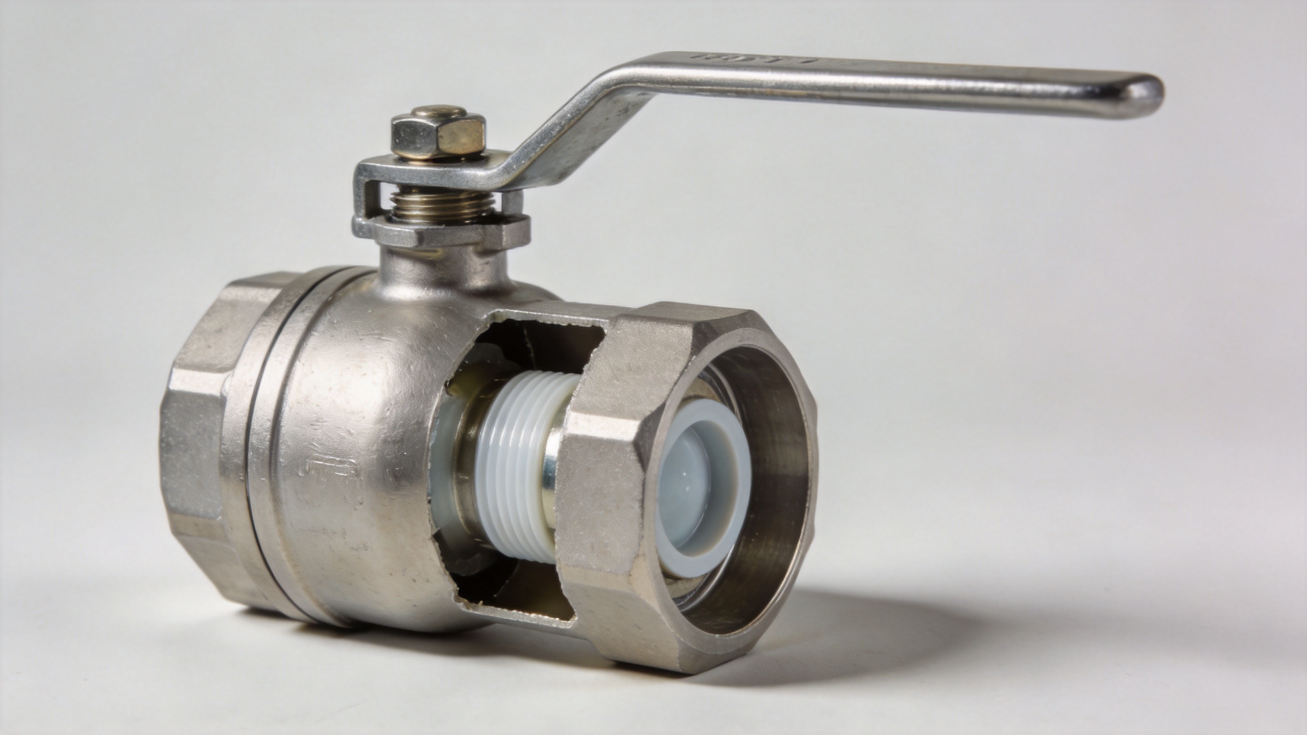
The flow-control element in a Manual Ball Valve is a spherical ball with a port through it. A handle attaches to the stem, and the stem transfers the operator’s quarter-turn motion to the ball. In the open position, the ball port follows the pipe axis. In the closed position, the solid side of the ball faces the flow path. This makes a Manual Ball Valve especially familiar for straightforward on/off duties where local operation is practical.
The design is usually described as a two-way valve because it controls flow between an inlet and an outlet. Three-way versions use a different port pattern and need a more careful flow-path review. Do not assume that every Manual Ball Valve offers the same bore, pressure-temperature range, or switching function. Full-port and reduced-port designs, for example, serve different system priorities.
The Structural Parts That Matter
Valve body and end connections
The body is the pressure-containing shell of a Manual Ball Valve. It holds the ball, seats, stem, and sealing elements in the required alignment. Body construction may be one-piece, two-piece, or three-piece, depending on the design. Those descriptions alone do not prove suitability; they simply indicate how the assembly is built and how maintenance access may be approached. Threaded, flanged, welded, and other end connections must match the piping design rather than be chosen from a catalog image.
Body material also requires a service-based decision. Material compatibility is tied to the medium, temperature, corrosion exposure, and project requirements. A Manual Ball Valve that is appropriate for clean water may need a different material and sealing review for a chemical process. Do not start by asking for a universally preferred body material; first write down the medium and operating conditions.
Ball, port, and seats
The ball is the moving closure member. Its surface works against seats placed between the ball and body, and those seats create the primary shutoff interface. In a Manual Ball Valve, seat selection affects leakage resistance, operating torque, wear behavior, and temperature limits. Soft seats are common in many services, while other seat constructions may be considered where the process conditions require them. The specification must identify the material and applicable limits instead of treating “ball valve seat” as a universal feature.
Port geometry affects flow behavior. A full-port Manual Ball Valve generally has a bore closer to the nominal pipe bore, while a reduced-port design has a smaller internal passage. The right choice depends on pressure-drop sensitivity, pigging needs where relevant, line velocity, cost, and the overall piping calculation. A single flow claim is not enough; the valve and the system must be reviewed together.
Stem, packing, and handle
The stem links the external handle to the internal ball. Stem sealing and packing are important because the stem passes through the body boundary. A well-specified Manual Ball Valve needs a stem arrangement that suits its pressure, temperature, cycling, and maintenance expectations. Handle length and operating torque also matter. If the required torque is too high for safe, repeatable manual use, an actuator or gearbox review may be more appropriate.
The lever provides visible position indication in many designs: broadly parallel to the pipeline when open and crosswise when closed. That convenience should not replace lockout procedures, operating instructions, or verification at the point of use. In a safety-critical duty, a Manual Ball Valve must be considered alongside isolation procedure, access, and the consequences of an incorrect position.
Manual Operation Versus Automation
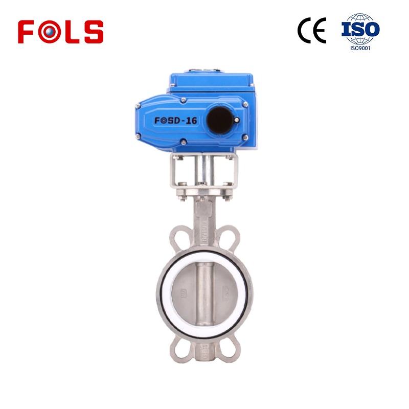
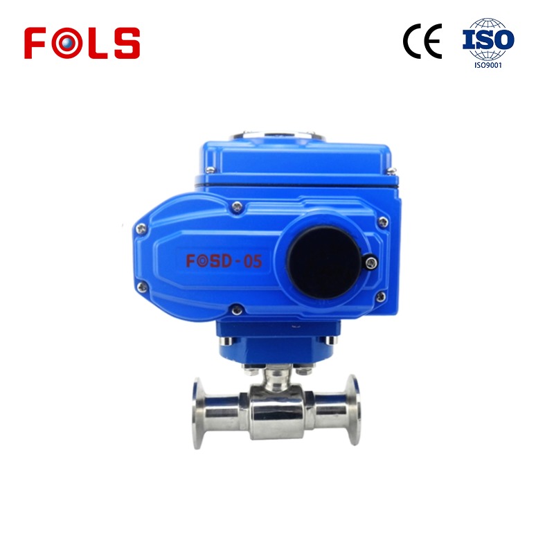
A Manual Ball Valve is often a sensible choice when operation is local, infrequent, and easy to reach. It can simplify a basic isolation point because no electrical supply, pneumatic source, or control signal is required for the turning action. However, manual operation is not automatically the low-risk choice. Remote access, repeated cycling, high torque, emergency response requirements, and integration with instruments can change the decision.
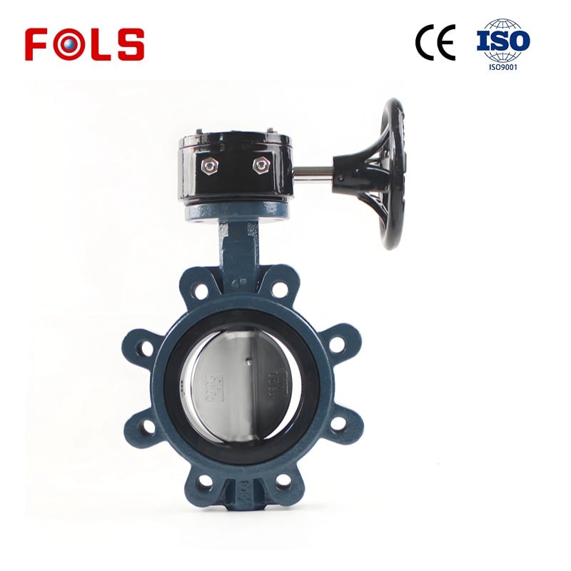
This is where nearby valve categories can confuse an initial search. Hygienic butterfly valves may be evaluated for sanitary process layouts, while an 8 butterfly valve query may concern line size rather than ball-valve construction. They should not be substituted into a Manual Ball Valve specification without checking the process connection, sealing, cleanability, flow-control objective, and required shutoff behavior.
What to Confirm Before Selecting One
For industrial purchasing, the strongest structural summary becomes a short confirmation list. Before ordering a Manual Ball Valve, confirm:
- the medium, concentration where relevant, operating pressure, temperature, and possible upset conditions;
- nominal size, end connection, face-to-face requirements, and whether full or reduced port is needed;
- body, ball, stem, seat, and seal materials, with the project compatibility review documented;
- two-way or three-way flow function and the intended open/closed position logic;
- manual operating torque, available access space, handle orientation, and lockout needs;
- the testing, documentation, and standards requirements specified for the project.
For applicable metal ball-valve projects, documents may reference standards such as API 608 or ISO 17292, but a reference to a standard is not a substitute for a project datasheet. The buyer should confirm which edition, scope, end connection, pressure class, inspection requirement, and material provisions apply to the particular Manual Ball Valve.
A Practical Structural Takeaway
A Manual Ball Valve is not merely a handle and a round closure. Its practical performance comes from the relationship between the body, end connections, ball, seats, stem, packing, and lever under a defined operating condition. That is why a component list alone is not enough for selection.
For a new line or a replacement, start with the process data, then map those conditions to the structure and operating method. If the conditions are stable and local operation is genuinely manageable, a Manual Ball Valve can be a direct and understandable on/off solution. If access, torque, cycle frequency, or control integration changes, the same valve body may require a different operating arrangement. Confirming that boundary early reduces avoidable specification changes later.
 Hot News





