
 EN
How Pneumatic Ball Valve Automates Industrial Pipelines
When a pipeline needs repeatable on/off control, a Pneumatic Ball Valve turns a manual isolation point into an automated part of the process. It combines a quarter-turn ball valve with an air actuator, so a control signal can command flow without sending an operator to the valve location. For maintenance teams and project engineers, the useful question is not simply whether automation is desirable. It is whether the valve body, actuator, air circuit, and failure response fit the actual duty.
From an automation-engineering perspective, it helps to treat the assembly as a chain rather than a single product. The ball valve handles shutoff; the actuator supplies torque and movement; a directional control valve routes air; and the control system decides when to open or close. If one link is mismatched, the system may still move, but it may not move safely or reliably under the intended conditions.
What a Pneumatic Ball Valve Does in a Pipeline
A Pneumatic Ball Valve uses compressed air to rotate the ball inside a quarter-turn valve body. In the open position, the ball bore aligns with the pipeline. In the closed position, the ball turns across the flow path to isolate the line. This simple motion makes the format common where a process needs frequent, remotely controlled shutoff.
The arrangement is particularly useful when valves are installed at height, inside guarded equipment, in wet areas, or across a distributed utility system. It can also reduce variation between shifts because the control logic, rather than an individual operator’s timing, determines the switching sequence. That does not make every pneumatic assembly interchangeable. Media compatibility, pressure, temperature, sealing material, valve size, available air pressure, and switching frequency still need confirmation.
The Automation Chain: From Signal to Valve Movement
Understanding the chain makes troubleshooting much faster. A typical installation contains four functional layers:
- Valve body: provides the flow path and shutoff function.
- Pneumatic actuator: converts air pressure into rotational movement for the valve stem.
- Air-control hardware: directs air to the appropriate actuator port and exhausts the opposite side.
- Command and feedback layer: connects PLC, relay, local controls, limit switches, or position feedback to the sequence.
For a double-acting actuator, one air path drives opening and another drives closing. The directional valve alternates the air supply between them. A spring-return actuator works differently: air moves it in one direction, while springs return it to the specified normal position when air is removed. The required normal position must be defined from the process hazard and operating logic; it cannot be assumed from the valve name alone.
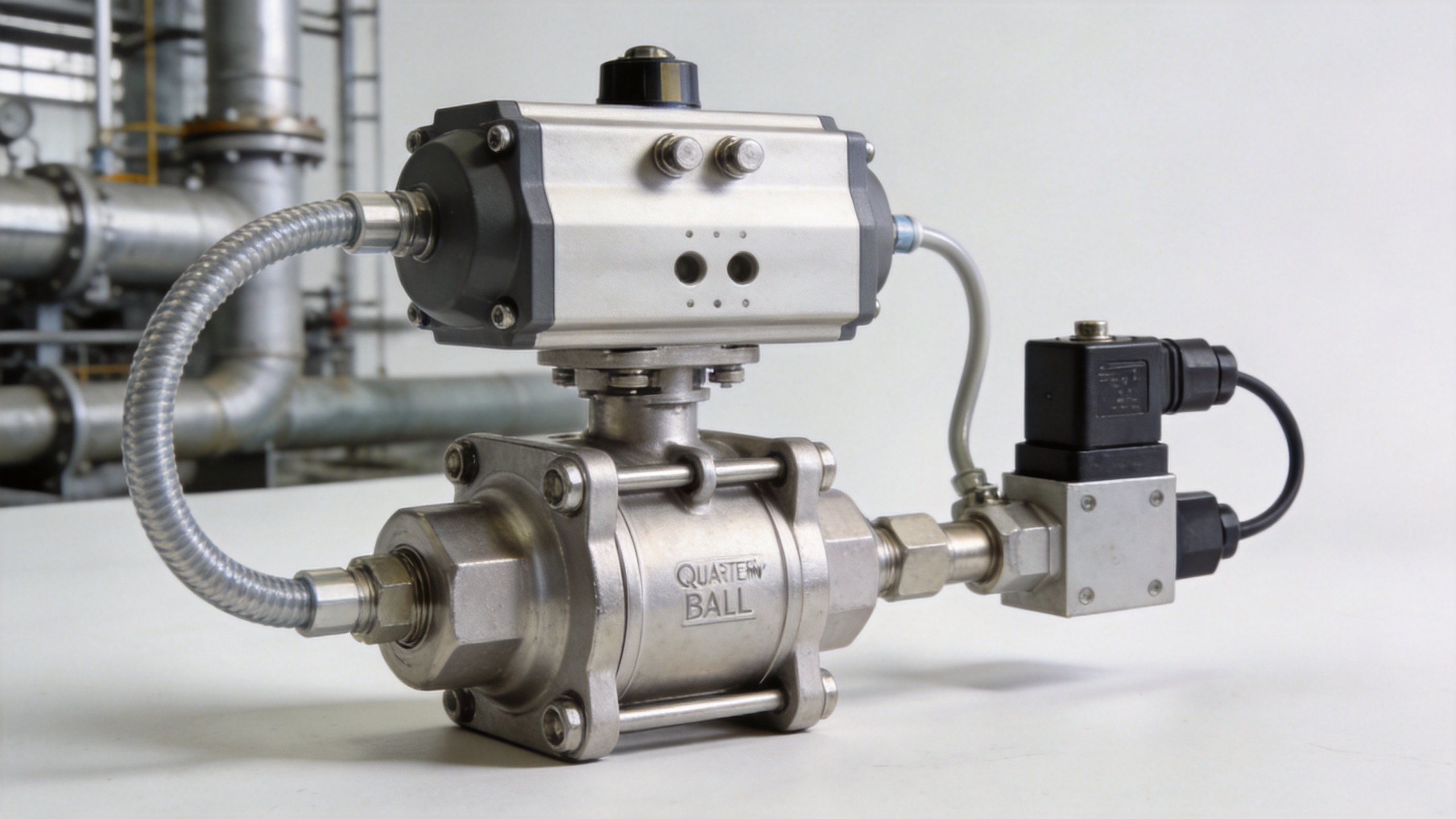
Where the Solenoid Valve Coil Fits
A solenoid valve coil is part of the control hardware, not normally part of the ball valve body itself. When energized, the coil shifts or pilots a directional valve so compressed air reaches the required actuator chamber. In a compact automated station, the coil may be one small component, but its voltage, enclosure, duty cycle, wiring, and response requirements can determine whether the command reaches the actuator consistently.
It is also important not to use solenoid coil as a catch-all description for every electrical part in the assembly. The coil creates the magnetic force that moves the solenoid valve mechanism; the solenoid valve then manages air; the actuator turns the valve. Separating these roles helps a buyer specify a Pneumatic Ball Valve package correctly and helps technicians isolate a fault. A valve that does not move may have a mechanical issue, insufficient air, a blocked pilot passage, an incorrect coil voltage, a wiring issue, or an interlock that is intentionally holding the command.
Choose the Actuator Action Before Ordering
One of the earliest decisions is actuator action. A double-acting design uses air for both directions and is often considered when the application has reliable air supply and needs powered open and powered close movement. A spring-return design uses air in one direction and springs in the other. It is considered when a defined response on loss of air is part of the process requirement.
There is no universal “better” action. For example, a line may need to close on loss of air to limit transfer, while another process may need to open for a safe drain or relief path. More accurately, the correct configuration depends on the medium, downstream equipment, cleaning sequence, maintenance plan, and the consequences of the wrong valve position. State the required fail position in the specification and verify the assembled valve action during commissioning.
Match Valve, Actuator, and Mounting Interface
The actuator must have enough torque to operate the chosen valve under the real differential pressure and seat conditions. Do not select only from nominal valve size. Breakaway torque, running torque, temperature effects, media deposits, operating frequency, and safety margin can all matter. A larger actuator is not automatically the answer either; oversizing can complicate control, mounting, and air consumption.
Mounting compatibility deserves its own line item. ISO 5211 is commonly used as an interface standard for quarter-turn actuator mounting, but the actual flange designation, stem connection, bracket, and coupling still need checking against the selected valve and actuator documentation. If the interface is unclear, ask for dimensional drawings rather than assuming that two components with similar labels will assemble correctly.
Build a Practical Specification Checklist
A useful request for quotation describes the process and the control boundary. Before selecting a Pneumatic Ball Valve, organize the following information:
- Medium, concentration, solids content, and cleaning requirements
- Operating and maximum pressure, temperature, and expected differential pressure
- Valve size, end connection, installation orientation, and available space
- Required flow behavior: isolation only, frequent cycling, or a defined sequence
- Available instrument-air pressure and air quality
- Double-acting or spring-return action, including the desired normal position
- Control voltage and the required solenoid valve coil configuration
- Need for limit switches, manual override, positioner, enclosure protection, or feedback
In procurement discussions, putting these points in writing usually prevents repeated clarification later. It also keeps the conversation focused on how the assembly will work in the pipeline rather than on a bare valve price alone.
Commissioning Checks That Prevent Avoidable Problems
Before placing an automated valve into service, verify that the pipeline is clean, the actuator is securely mounted, and the air supply is within the specified range. Cycle the valve locally before enabling automatic commands. Confirm both travel-end signals if feedback is used, and observe whether the valve reaches the intended position when the command is removed or air supply is isolated.
Then test the sequence with the connected equipment. A Pneumatic Ball Valve may be mechanically sound but still be timed incorrectly in a pump, tank, or batching sequence. Document the valve tag, normal state, control voltage, actuator action, air regulator setting, and any manual override procedure. Those small records make future maintenance safer and less dependent on memory.
Common Mistakes to Avoid
- Choosing a valve body before defining the medium and pressure conditions.
- Assuming the actuator’s default movement provides the required fail position.
- Treating a solenoid coil replacement as proof that the entire air-control circuit is healthy.
- Ignoring air quality, tubing routing, exhaust restrictions, or regulator settings.
- Ordering without confirming the mounting interface, stem coupling, and torque basis.
- Using remote control without testing feedback and interlocks during commissioning.
Conclusion
A Pneumatic Ball Valve automates an industrial pipeline by linking quarter-turn shutoff to an air-powered actuator and a defined control signal. The strongest results come from specifying the whole system: the process duty, valve construction, actuator action, air supply, solenoid valve coil, mounting arrangement, and feedback plan. When those items are verified together, automation becomes a controlled engineering decision rather than an add-on with unanswered questions.
 Hot News





