
 EN
How Does Wafer Butterfly Valve Fit Pipe Flanges?
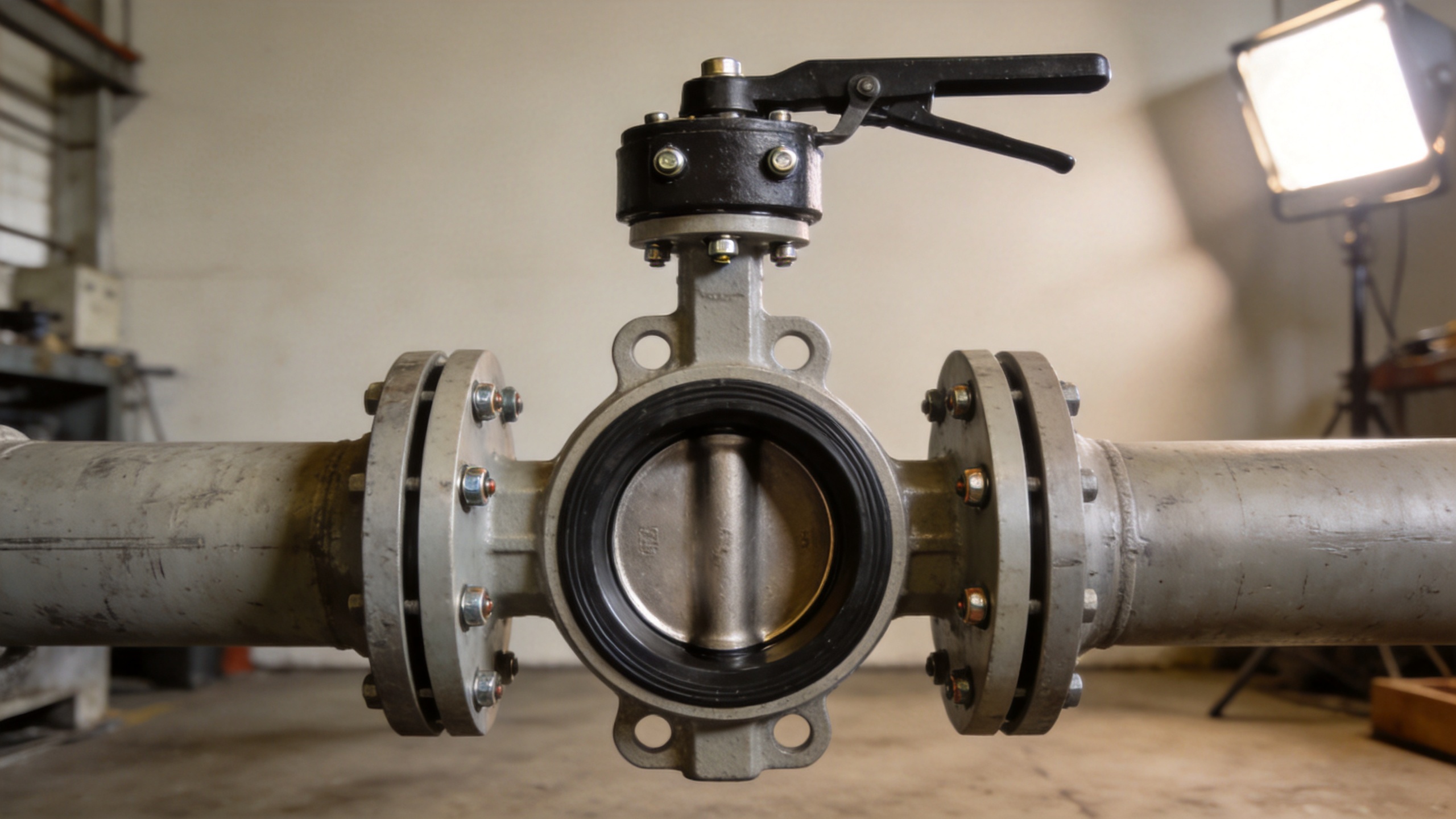
A Wafer Butterfly Valve fits between two matching pipe flanges rather than bolting to flanges cast into the valve body. The pipe flanges, bolts, nuts, and compressed seat work together as one joint. That compact arrangement is why a Wafer Butterfly Valve is common where installation space and component weight matter, but it also means centering and bolt loading deserve careful attention.
From a valve application engineer’s viewpoint, the useful question is not only whether the nominal size matches. It is whether the flange faces, bore clearance, seat design, disc travel, bolt pattern, service conditions, and installation procedure work together. The following explanation describes the general arrangement; the valve manufacturer’s instructions and the project specification remain the controlling documents for a particular installation.
The basic flange-to-valve arrangement
A Wafer Butterfly Valve has a thin body with a resilient or engineered seat around its flow bore. It is placed between two pipe flanges and retained when the flange bolts are installed and tightened. Unlike a flanged-end valve, the body does not provide its own pair of full bolt-up flanges. Unlike many lug-body designs, a standard wafer body is not normally intended to support one side of the line after the other side has been removed.
During installation, the pipe flanges provide the clamping faces, the bolts provide the holding force, and the seat seals against the flange faces when compressed as intended. Locating holes or alignment lugs on the Wafer Butterfly Valve help position the body while the hardware is installed. They are positioning features, not a substitute for checking the whole joint.
Why centering matters before any bolt is tightened
The valve bore should be concentric with the flange bores, and the disc must have enough clearance to rotate without touching the pipe or flange. A Wafer Butterfly Valve that sits low, high, or off-center may look acceptable while the bolts are loose yet bind when the disc is cycled. That is a system issue, not merely a valve issue.
Start with a visual check of both flange faces. Remove debris, weld spatter, damaged gasket material, and anything that could create a local high spot. Confirm that the flanges are parallel enough for the assembly procedure and that the pipe ends do not intrude into the disc path. Do not use the flange bolts to pull severely misaligned pipe into place; doing so can load the body and seat unevenly.
For a resilient-seated Wafer Butterfly Valve, the seat may serve as the sealing element in a compatible flange connection, but that depends on the model and service. Adding a gasket automatically is not a universal improvement. A gasket choice, if one is required, should follow the valve documentation and line specification because it changes the compression stack and available disc clearance.
A practical installation sequence
- Verify the joint components. Check the valve size, pressure class or rating basis, flange standard, bolt pattern, bolt length, and service compatibility against approved documents. The same nominal size alone is not enough to establish fit.
- Set the disc position. Place the disc slightly open when positioning a Wafer Butterfly Valve, unless the manufacturer specifies another position. This helps protect the seat during insertion while allowing the installer to verify that the disc will not strike adjacent bore edges.
- Open the flange gap only as needed. Support the pipework and spread the flanges enough to insert the body without scraping or stretching the seat. Excessive spreading can create its own alignment problem.
- Use the locating features and temporary bolts. Insert guide or alignment bolts where the design permits, bring the Wafer Butterfly Valve to the center of the bore, and check that the actuator, handle, and any accessories have the required clearance.
- Bring the flanges together evenly. Install the remaining bolts finger-tight first. Check the disc travel before final tightening. If the disc touches, stop and correct the alignment rather than forcing operation.
- Tighten in a cross pattern. Increase bolt load progressively and evenly according to the approved torque procedure. Uneven loading can distort a resilient seat or leave one segment insufficiently compressed.
- Cycle and inspect. Operate the Wafer Butterfly Valve from closed to open and back before commissioning. Then inspect the flange joint, accessible fasteners, and the actuator or handle for interference.
What the bolts do—and what they should not do
In a wafer installation, the through-bolts clamp the two flanges and retain the Wafer Butterfly Valve in the line. They should not be used as correction tools for bent pipe, incompatible flange faces, or an incorrect valve size. Tightening one side to “pull the valve over” can produce uneven seat compression and make a later leak or operating problem harder to diagnose.
There is no responsible generic torque number for every Wafer Butterfly Valve. Required torque depends on valve construction, nominal size, flange facing, fastener diameter and grade, gasket arrangement if applicable, lubricant condition, and the project procedure. Use the current model-specific installation instructions and the approved bolting specification. If those documents disagree, resolve the discrepancy before the joint is commissioned.
Flange compatibility checks that reduce rework
Before selecting or installing a Wafer Butterfly Valve, confirm the flange standard and face geometry, not just the pipe size. Verify that the bolt pattern allows the body to be retained correctly and that the flange inside diameter provides disc clearance. Large bore variations, raised features, liners, or pipe welds can matter. This is particularly important when a valve is being substituted into an existing line.
Also consider what happens around the valve after installation. An actuator needs room for travel and maintenance. A handle needs a usable operating arc. A heavy actuator may need support rather than relying on the valve neck and adjacent piping alone. These details often determine whether a compact Wafer Butterfly Valve arrangement stays practical throughout service.
Wafer body versus lug body: the isolation question
A Wafer Butterfly Valve is retained by clamping between two flanges, so it is generally evaluated as part of a continuous, supported pipeline joint. A lug-style valve has threaded or through lugs that can support different piping arrangements, subject to the manufacturer’s stated pressure and end-of-line limitations. The choice is not about one body style being universally preferable; it is about the maintenance and isolation conditions the line must accommodate.
Related components should not be treated as interchangeable simply because they share the word “wafer.” For example, buyers comparing wafer check valve manufacturers should verify face-to-face dimensions, retention method, flange compatibility, service medium, and installation orientation for each check-valve design. A wafer spring check valve uses a different internal function and may have its own flow-direction and opening-characteristic requirements. It does not change how the butterfly valve’s flange joint must be aligned and tightened.
Pre-commissioning checklist
- Flange standard, nominal size, face condition, and bolt pattern have been confirmed.
- The Wafer Butterfly Valve is centered and the disc moves freely through its full travel.
- Seat, flange faces, and any specified gasket arrangement match the approved installation instructions.
- Bolts have been tightened in the documented cross pattern to the applicable procedure.
- Pipe supports, actuator clearance, handle access, and maintenance space have been checked.
- The line is pressurized and inspected using the project’s commissioning process.
Key takeaway
A Wafer Butterfly Valve fits pipe flanges by being sandwiched and centered between them, with the flange bolting retaining the valve and loading the sealing contact area. Good results depend on more than inserting the body between two pipes: verify compatibility, protect disc clearance, tighten evenly, and use model-specific installation instructions for torque and commissioning details. When those checks are visible before startup, the compact wafer connection is easier to install, inspect, and maintain.
 Hot News





