
 EN
How Does Control Valve Regulate Industrial Processes?
In an industrial loop, a Control Valve is the final element that turns a controller’s decision into a physical change in the process. It does not merely open or close a pipe. A properly applied Control Valve changes the resistance to flow so that the process can move toward a required flow, pressure, temperature, or level condition.
From an automation-control perspective, the useful question is not simply “which valve is suitable?” It is how the valve body, actuator, feedback signal, and process conditions work together. The sections below explain that sequence and the checks that keep a Control Valve discussion tied to real operating conditions.
The Control Loop Behind a Control Valve
A Control Valve normally operates as part of a closed loop. A sensor measures a process variable, such as outlet pressure or tank level. The controller compares that measurement with a setpoint and sends an output signal. An actuator receives the signal and moves the valve stem, shaft, plug, ball, disc, or other closure member. That movement changes the flow passage through the Control Valve.
If a heat exchanger outlet is cooler than the target temperature, for example, the controller may call for more heating medium. The actuator then moves the Control Valve toward a position that permits more flow. The new flow changes the heat transfer, the sensor reports the result, and the controller continues to adjust as needed. The valve is therefore part of a repeating feedback action, not an isolated item.
The direction of movement depends on the process objective and valve action. More opening can increase flow in one installation, while a different piping arrangement or a reverse-acting actuator can require the opposite response. This is why signal action, installed flow direction, and fail position need confirmation before a control philosophy is finalized.
How the Valve Changes the Process
When a Control Valve moves, it changes the available flow area and the pressure loss across that point in the line. In broad terms, a smaller effective opening raises resistance and restricts flow; a larger opening lowers resistance and allows more flow when the rest of the system supports it. The resulting flow is also influenced by upstream and downstream pressure, fluid properties, pipe geometry, and other restrictions.
A Control Valve can therefore influence more than flow rate. In a level loop, inlet or outlet flow affects liquid inventory. In a pressure loop, the pressure drop assigned to the valve affects the controlled pressure. In a temperature loop, changing steam, cooling water, thermal oil, or process-fluid flow alters heat transfer. The valve responds to a command, but the process response determines whether the loop is actually stable and useful.
That distinction matters during selection. A single pressure rating or nominal size does not describe control quality by itself. The valve, actuator, controller tuning, sensor location, and process dynamics all contribute to the result.
Valve Body, Trim, Actuator, and Position Feedback
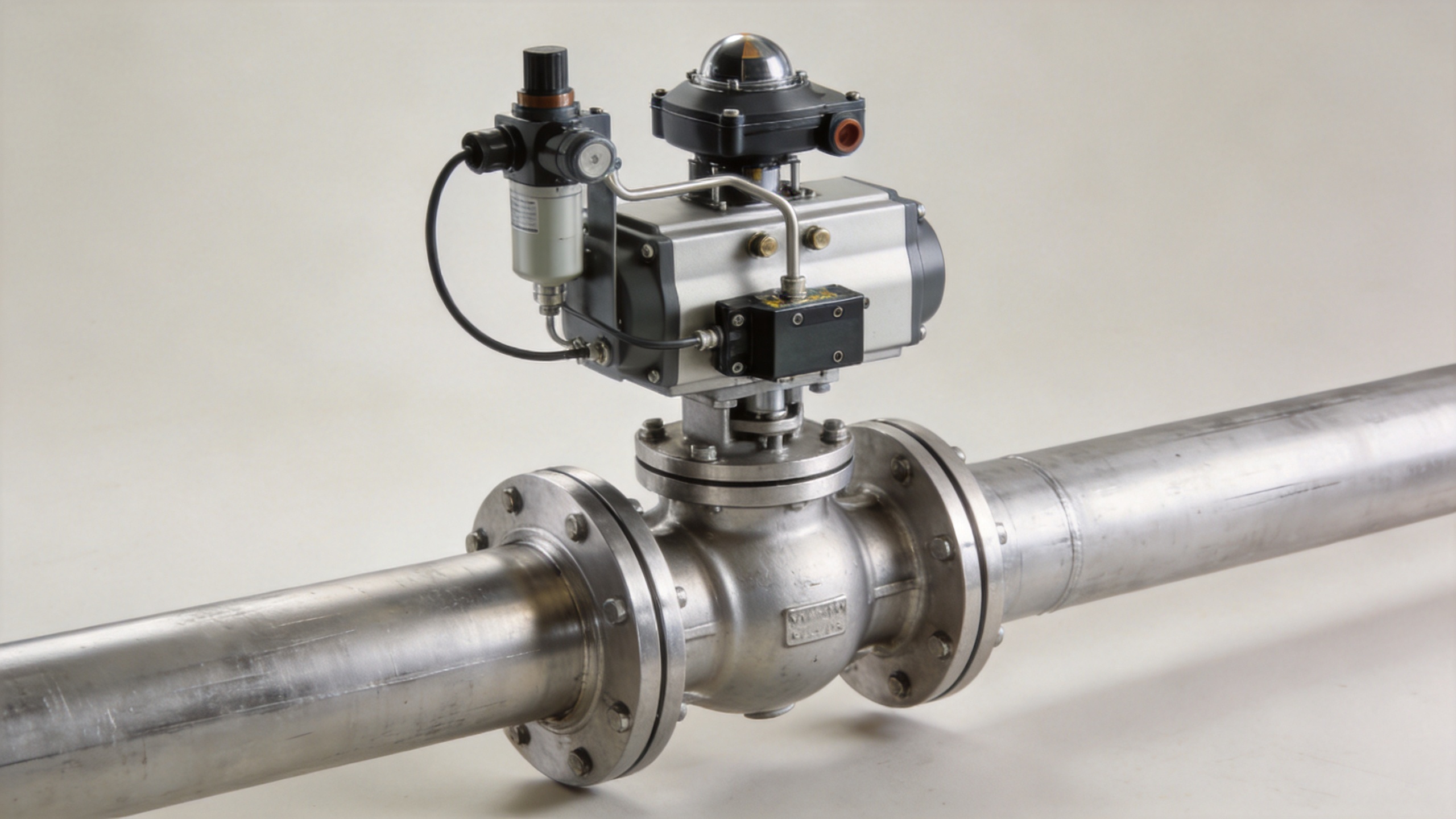
The body and trim define the wetted flow path of a Control Valve. Depending on the duty, the closure member may be a globe-style plug, rotary ball, butterfly disc, or another geometry. The actuator supplies the force or torque to position that closure member. Pneumatic, electric, and hydraulic actuation are different ways to create that motion; the choice should match available utilities, required speed, thrust or torque, and the intended response to a loss of signal or power.
A positioner can compare commanded travel with actual stem or shaft position and correct the actuator output. In modulating service, this can help the Control Valve follow the controller’s requested position more closely. It does not remove the need to assess friction, travel limits, air or power quality, and the installed process conditions.
Flow characteristic is another important part of the discussion. A valve’s inherent characteristic is measured under specified test conditions, whereas installed behavior is affected by the real piping system and changing pressure drop. Linear and equal-percentage descriptions can be useful selection language, but neither label alone determines how a Control Valve will behave in a particular loop. The expected operating range and system resistance need review.
Modulating Control Versus On/Off Isolation
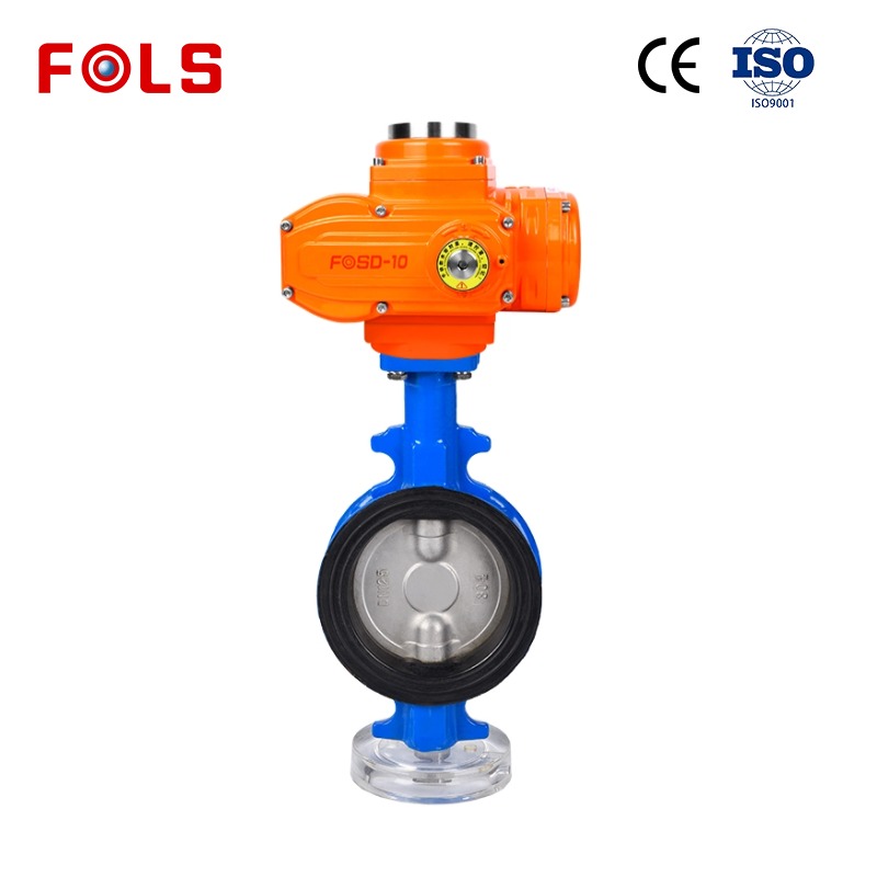
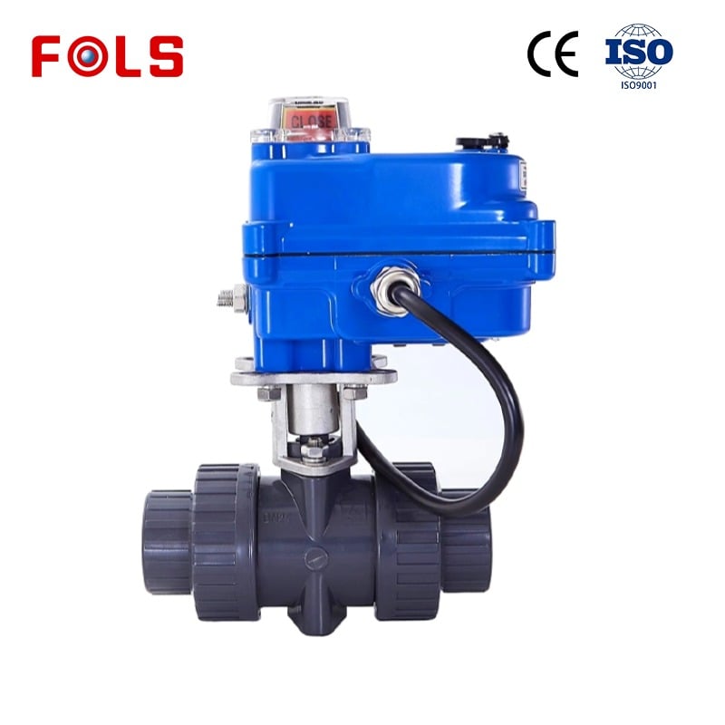
Not every automated valve is intended to throttle. A 2 port motorised valve may be specified for simple open/close isolation, zone switching, or batch sequencing. In that role, it may receive a discrete command and travel to one end position. That is different from a Control Valve that repeatedly takes intermediate positions to regulate a process variable.
The distinction should not be based on the product name alone. Some motor-operated assemblies can be configured for modulating duty, while some valve designs are intended primarily for isolation. Ask whether the control signal is on/off or proportional, how often movement occurs, what accuracy is needed, and whether a defined fail position is required. A 2 port motorised valve should be evaluated against those conditions rather than assumed to provide the same control behavior as a throttling Control Valve.
Pressure Drop, Stability, and Liquid-Service Limits
A Control Valve needs enough pressure drop to influence flow, yet excessive pressure drop can create operating concerns. In liquid service, local pressure can fall below the liquid’s vapor pressure. If vapor bubbles form and pressure later recovers, their collapse is associated with cavitation. If the pressure remains below vapor pressure downstream, the condition is generally described as flashing. Both conditions call for a focused review of the process data, trim concept, materials, noise, and downstream arrangement.
A pressure compensated flow control valve addresses a more specific need: maintaining relatively consistent flow despite pressure changes within its design conditions. It is not a universal substitute for a general process Control Valve. Its suitability depends on the fluid, allowable differential pressure, required accuracy, contamination exposure, and the rest of the hydraulic or process circuit. If the service is variable or severe, sizing and application details need engineering confirmation.
A Practical Information Checklist
Before discussing a Control Valve configuration, organize the information that governs the control loop:
- Process fluid, including possible solids, corrosion, vapor pressure, and changes in composition.
- Normal, minimum, and maximum flow; upstream and downstream pressure; and operating temperature.
- Required controlled variable, setpoint range, and whether the duty is modulating or on/off.
- Valve connection, installation orientation, available maintenance space, and accessibility.
- Available pneumatic, electric, or hydraulic energy and the required fail action.
- Control signal, feedback expectation, cycle frequency, and documents that need review.
In practice, a Control Valve is only one part of the control chain. Treating the actuator as an afterthought can leave fail action, available energy, and signal compatibility unresolved. Likewise, matching a valve size to the pipe without reviewing the operating flow range can leave the valve with little useful travel where control is needed.
Conclusion
A Control Valve regulates an industrial process by translating a controller signal into a measured change in flow resistance. The changed flow then affects the variable being controlled, and feedback guides the next adjustment. For a reliable application discussion, begin with fluid conditions and process objectives, then examine valve capacity, characteristic, actuator, signal connection, pressure drop, and fail action together. That sequence provides a clearer basis for evaluating a Control Valve, a 2 port motorised valve, or a pressure compensated flow control valve in the right role.

 Hot News





