
 EN
How Does 3-Way Ball Valve Divert Fluid Paths?
A 3-Way Ball Valve gives a piping system a controlled choice: send one incoming stream toward one of two outlets, combine two streams toward one outlet, or establish a bypass path. Unlike a two-port isolation valve, it uses three body ports and a drilled ball. When the stem turns the ball, the internal passage lines up with a different set of ports. That simple movement is why a 3-Way Ball Valve is often considered when a process needs routing rather than only on/off isolation.
From an industrial valve application engineer’s perspective, the useful starting point is not the valve name. First identify the medium, pressure, temperature, line size, required flow direction, and whether the changeover is manual or automated. A 3-Way Ball Valve may look compact on a diagram, but its correct flow path, seat material, and actuator position still depend on the actual duty.
What changes inside a 3-Way Ball Valve?
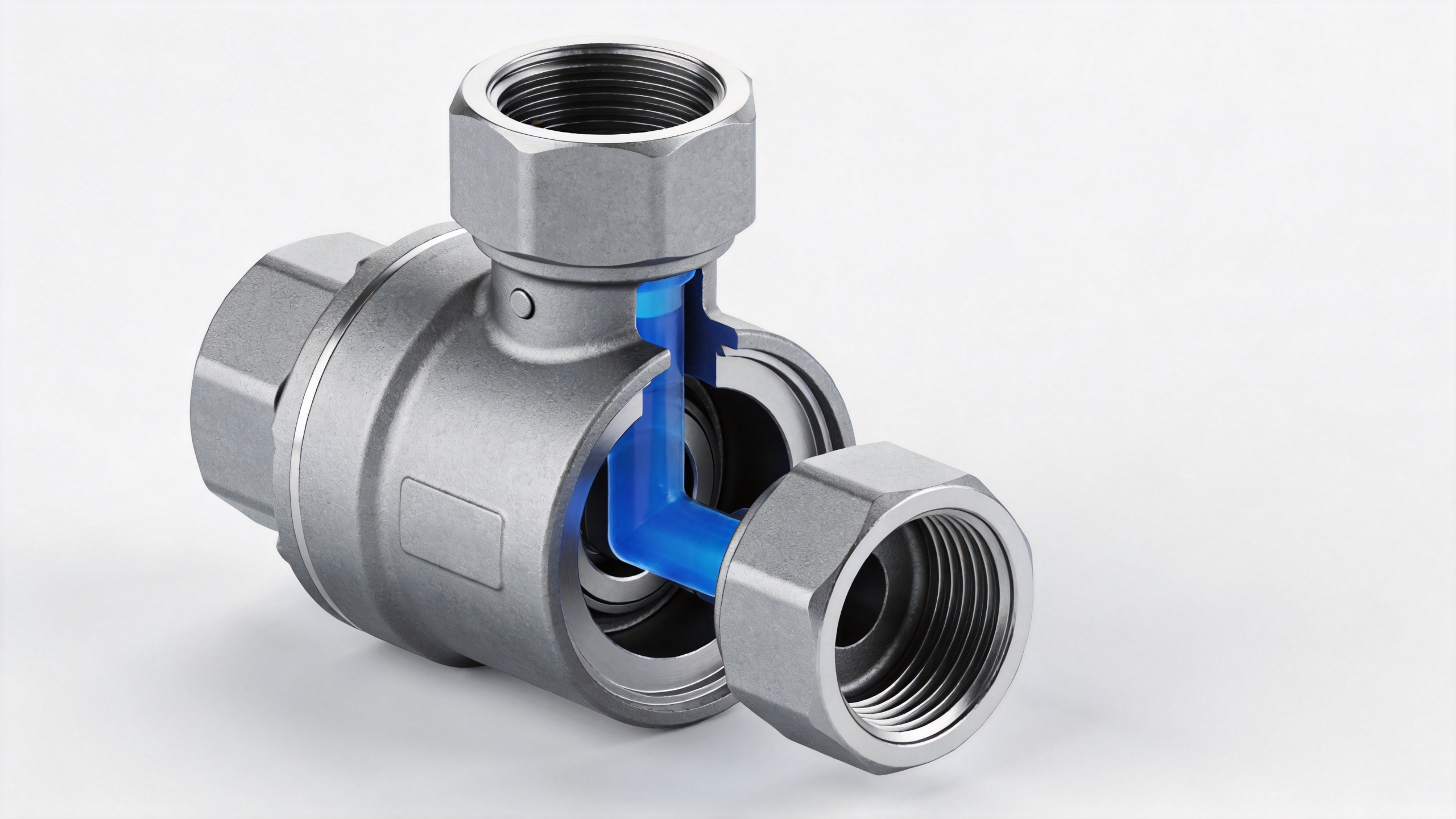
The ball contains a shaped bore rather than the straight-through bore found in a conventional two-way valve. Three ports enter the valve body, often identified as a common port and two branch ports. Rotating the handle or actuator changes which ports are connected. The ball does not create flow; it creates or blocks internal passages so the pressure difference already present in the system can move the fluid along the selected route.
For a diverting duty, fluid enters the common port and the 3-Way Ball Valve connects it to one selected branch. For a mixing duty, two inlet streams may be directed through the valve toward a common outlet, subject to the selected port pattern and operating position. Exact port labels and permitted positions vary by design, so the manufacturer’s flow diagram should govern installation and automation logic.
L-port: one inlet, one selected outlet
An L-port, also called an L-pattern, has an internal passage shaped like the letter L. In a typical diverting arrangement, it connects the common port to one side port in one handle position and to the other side port after a quarter turn. The two branch ports are not normally connected to each other at the same time. This makes an L-port 3-Way Ball Valve a practical starting point for switching a stream between two destinations, such as a service line and a return line.
A useful field check is to stop relying on “left” and “right” descriptions. Mark the body ports, review the flow schematic, and then map each handle or actuator position to the actual connected pair. Pipe orientation can make a correct L-port valve appear reversed if the drawing and body markings have not been reconciled.
T-port: more routing possibilities, more checks
A T-port ball contains a T-shaped passage. Depending on the ball design and rotation range, a T-port 3-Way Ball Valve can connect the common port to either branch, connect all three ports in a mixing or distribution position, or provide a shutoff position. Not every T-port offers every pattern; some are built for mixing, some for diverting, and some have limited positions. The port diagram is therefore part of the specification, not an optional detail.
The extra routing flexibility can be valuable for a bypass, blending point, or alternate process path. It also raises the importance of position control. If the process must not place two sources in communication, specify a ball pattern and actuator travel that rule out that position. An electric or pneumatic actuator should be selected together with the valve so its travel stops, control signal, and fail position match the process requirement.
Why a 3 way gate valve is not the same solution
A search for a 3 way gate valve can create confusion during early selection. Gate valves are generally associated with linear gate movement and isolation duties, while a 3-Way Ball Valve is a quarter-turn multi-port routing device. They should not be treated as interchangeable merely because both descriptions contain “three way.” Compare the required flow paths, switching frequency, pressure drop expectations, operating speed, and maintenance access before choosing a valve type.
Where does a three piece ball valve fit?
A three piece ball valve describes a body construction, usually one designed so the center section can be removed for service while pipe ends remain installed. It does not, by itself, identify a three-port routing pattern. A three piece ball valve can be two-way or multi-port depending on its design. When maintenance access matters, ask separately about body construction, end connections, seat replacement procedure, and whether the selected 3-Way Ball Valve has a serviceable configuration.
Five checks before specifying the flow path
- Draw the duty. Identify every source, destination, normal flow direction, and prohibited connection.
- Choose the port pattern. Select L-port for a simple changeover when its positions match the duty; evaluate T-port where mixing, bypass, or broader routing is needed.
- Confirm materials. Body, ball, seat, and seal compatibility must be reviewed for the medium, temperature, pressure, and cleaning or corrosion conditions.
- Define the operating position. Record what each handle position or actuator signal connects. For automatic service, identify the intended fail position.
- Verify interfaces. Check bore, connection type, pressure-temperature rating, actuator mounting, control voltage or air supply, and available maintenance space against the applicable datasheet.
Turn the valve question into a usable inquiry
A clear inquiry makes it easier to evaluate a 3-Way Ball Valve without assuming an unverified configuration. State the medium, flow direction diagram, pipe size, pressure and temperature range, connection standard, preferred body and seat materials, manual or actuated operation, and required fail position. If the system needs a bypass or blending position, include that condition in the sketch. Saying “three way” alone is not enough to determine whether an L-port or T-port pattern is suitable.
In short, a 3-Way Ball Valve diverts fluid because its rotating ball selectively connects internal passages between three ports. The right design turns that basic mechanism into a controlled routing function; the wrong pattern can create an unwanted connection or fail to provide the required path. Start with the piping logic, then verify materials, ratings, and actuation against the product documentation for the actual service.
 Hot News





