
 EN
Electric Butterfly Valve in Municipal Water Supply Networks
Municipal water systems need valves that can isolate sections, support operating changes, and remain serviceable over a long asset life. An Electric Butterfly Valve can be a practical choice where operators need quarter-turn movement with remote command or automated sequencing. The useful question is not simply whether an electric actuator can open a disc; it is whether the complete valve, actuator, control package, and installation conditions fit the network duty.
From an application-engineering viewpoint, specification should begin with the line’s function and differential-pressure conditions rather than with a generic actuator catalog. This article sets out the checks that help a water utility, consulting engineer, or gate valve supplier assess an Electric Butterfly Valve for a municipal project.
Start with the duty in the water network
Municipal networks contain transmission mains, treatment-process lines, reservoir connections, pump stations, and distribution zones. Each location imposes a different operating pattern. A valve that normally stays open and closes only for planned isolation has different requirements from one that cycles frequently for a control sequence.
Document the medium, line size, expected pressure range, maximum differential pressure across the closed disc, temperature range, flow direction if relevant, and the intended role: isolation, throttling, emergency action, or automated sequencing. Also record upstream and downstream piping geometry, because disturbed flow and nearby fittings can affect how a valve behaves in service.
For waterworks applications, project teams can use current standards as a verification route rather than assuming compliance from a product label. The AWWA standards list includes C519-25 for high-performance waterworks butterfly valves in the 3 in. (75 mm) through 60 in. (1,500 mm) range. Retrieved AWWA material also describes C504 as covering rubber-seated butterfly valves from 3 in. (75 mm) through 72 in. (1,800 mm). Confirm the edition, scope, materials, test requirements, and project specification with the responsible engineer before release.
Why electric actuation changes the selection process
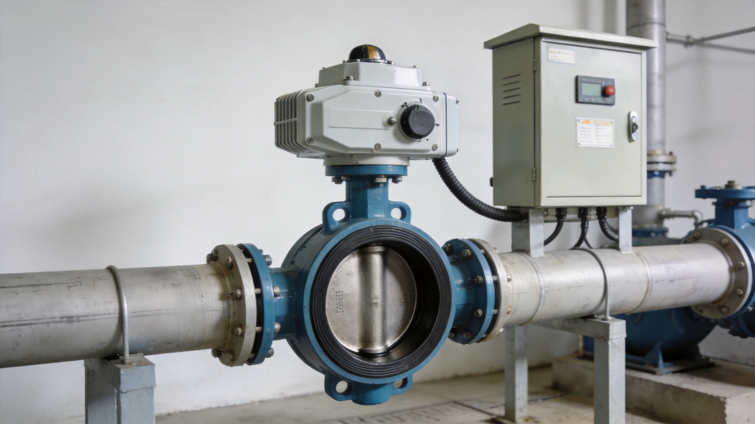
An Electric Butterfly Valve combines a quarter-turn valve with an actuator, electrical supply, controls, limit setting, and local operating provision. That combination can reduce the need for manual intervention at dispersed sites and can support supervised operation from a control system. It also introduces interface questions that should be resolved before procurement.
- Torque: Size the actuator for the actual valve torque over the required operating conditions, including seating, breakaway, running torque, pressure differential, and margin defined by the project. Do not substitute a nominal actuator output for a duty calculation.
- Power and failure behavior: Identify supply voltage, phase, enclosure needs, backup power strategy, and the required position or response when power is lost. “Fail safe” should describe a verified project function, not a generic expectation.
- Controls: Define on/off or modulating duty, local/remote selector logic, position feedback, interlocks, communication signals, and any SCADA integration requirements.
- Field access: Verify handwheel or manual override access, actuator removal clearance, cable entry orientation, and safe maintenance isolation.
Retrieved actuator-selection guidance likewise emphasizes matching the actuator to real valve torque, operating conditions, and control requirements. This is especially important when a Municipal Water Supply Network has pressure zones or pump-operation scenarios that differ from normal steady flow.
Match the valve construction to the actual water duty
The disc, seat, shaft, body material, coating, end connection, and bearing arrangement should be reviewed as a system. A specification should distinguish potable-water, raw-water, and treated-water duties where the owner’s requirements differ. It should also state the required dimensional standard, pressure class, face-to-face requirement, flange drilling, and sealing material rather than leaving a supplier to infer the full configuration.
A practical review has three stages. First, confirm the line conditions and isolation objective. Second, confirm the valve’s submitted drawings, material list, pressure rating, and test documents against that duty. Third, confirm that the electric actuator’s torque and control arrangement apply to the selected valve rather than to a similar-size example. This traceable path is more reliable than comparing only a valve diameter and an initial price.
Where butterfly valves fit beside gate and knife-gate options
A comparison with other isolation valves should be conditional. A gate valve supplier may recommend a gate valve where the system specification, bore requirement, or operating practice calls for it. A knife gate design is commonly evaluated for services involving solids or slurry; it should not be treated as a direct substitute for a clean-water isolation duty without reviewing the medium, sealing demand, and owner specification.
An Electric Butterfly Valve is often considered when compact quarter-turn operation and remote actuation are important. That does not make it the automatic answer for every line. The project team should compare pressure duty, shutoff requirements, hydraulics, maintenance access, actuator controls, and lifecycle impact for the exact installation. A short comparison table in the procurement package can prevent an unsuitable “like-for-like” substitution later.
Build a procurement and commissioning checklist
Good outcomes depend on clear handoff between engineering, procurement, installation, and operations. Before ordering, request the following project-specific confirmations:
- Valve size, connection, pressure rating, body and disc materials, seat material, coating, and applicable standard or specification clause.
- Calculated or verified torque basis at the stated differential pressure, plus actuator output and selected safety margin.
- Electrical supply, enclosure or environmental protection requirements, control mode, position feedback, local controls, and communications interface.
- Required close/open time and confirmation that the operating sequence avoids unacceptable surge or process effects.
- Manual override method, access envelope, lifting points, cable routing, commissioning tests, and spare-parts expectations.
- Document package: drawings, wiring diagram, actuator settings, test certificates where specified, installation instructions, and maintenance guidance.
During commissioning, verify travel limits, local and remote commands, feedback signals, interlocks, rotation direction, and safe isolation procedures. Record the as-built actuator settings so future maintenance does not rely on assumptions. This is also when the utility can check that the installed Electric Butterfly Valve matches the approved configuration.
Make the decision around verifiable operating conditions
A useful specification for an Electric Butterfly Valve in a municipal water supply network is not necessarily the longest one. It is the one that connects duty conditions, valve construction, actuator torque, controls, and maintenance access in a form that the owner and supplier can verify. FOLS Valve’s stated focus on industrial valves, electric actuators, and automatic control systems makes a condition-based technical discussion possible; final configuration should still be confirmed against the project’s drawings and documented service conditions.
By treating remote operation as a complete system requirement—not just an actuator add-on—municipal teams can compare alternatives more clearly and create a commissioning plan that supports reliable network isolation over time.
 Hot News





