
 EN
What Makes Solenoid Valve Perfect For Automation?
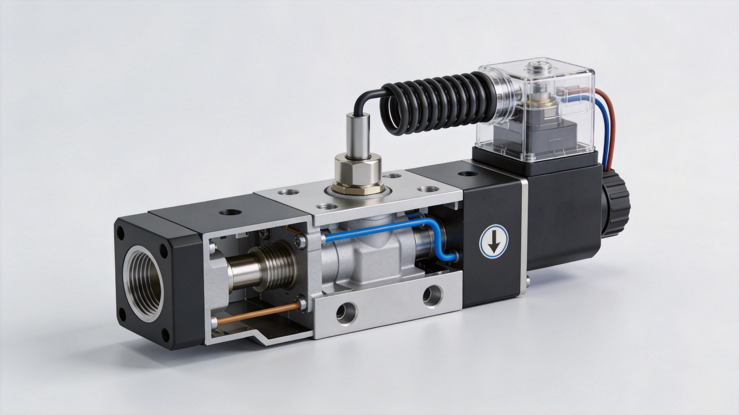
In a control system, a Solenoid Valve does one useful job very well: it turns an electrical command into a repeatable flow action. A PLC, relay, sensor, or safety circuit energizes a coil; the magnetic field moves a plunger or pilot mechanism; and the valve changes the path of air, water, gas, or another compatible medium. That direct relationship is why a Solenoid Valve appears so often in machine sequences, utility skids, dosing stations, and process-support equipment.
The headline needs a qualification. A Solenoid Valve is a strong automation fit when the duty is discrete open/close control and the valve is selected for the actual pressure, medium, voltage, environment, and safety function. It is not automatically the right choice for proportional control, severe contamination, or a large flow path that needs very low pressure loss. The practical value comes from matching the device to the control task.
Why a Solenoid Valve Works Naturally With Automated Control
Automation depends on clear signals and predictable states. A Solenoid Valve usually has a defined de-energized position and a defined energized position. That makes the valve easy to connect to a sequence: a level switch calls for fill, a controller starts a rinse cycle, or a safety relay removes power. The electrical input is simple to monitor, and the state logic can be documented in an I/O list.
Fast, compact actuation is another reason a Solenoid Valve is widely used. The coil can be driven by an appropriately rated AC or DC supply, while the valve body handles the fluid path. This separation lets designers place the electrical command within an existing cabinet-and-field-device architecture instead of adding a large mechanical actuator for every small on/off point.
For pneumatic automation, a Solenoid Valve may control pilot air that moves a larger actuator. In liquid or gas service, it may control the medium directly. In either case, the design team can map the valve’s normal position to the desired process state: normally closed for a line that should remain shut without power, or normally open where flow must continue until a command changes it. That choice is functional, not cosmetic, and should be reviewed with the process and safety teams.
The Features That Make a Solenoid Valve Useful in Real Systems
1. A clear electrical-to-flow connection
A Solenoid Valve accepts a discrete electrical instruction, which aligns with common PLC outputs, relay contacts, interposing relays, and control panels. It can therefore become a small but important link between the automation program and a physical process. Engineers should still confirm coil voltage, inrush and holding current, connector style, cable routing, and the output module’s switching capability.
2. Compact installation near the point of use
Locating a Solenoid Valve close to a cylinder, dosing point, burner train, or equipment branch can reduce the amount of tubing or pipe that remains between the command point and the action point. It also gives maintenance personnel a distinct component to isolate, inspect, and replace. Compactness does not remove the need for access; a coil, manual override if present, wiring connector, and service fittings should remain reachable.
3. Repeatable on/off duties
Where the process needs a binary decision rather than a continuously variable flow rate, a Solenoid Valve is usually easier to integrate than a throttling device. Typical tasks include admitting air to a pneumatic actuator, starting a wash-water pulse, isolating a utility branch, or providing a permissive-controlled gas shutoff function. Cycle frequency, energized duration, and coil temperature must be compatible with the intended duty cycle.
Selection Details That Decide Whether Automation Is Reliable
The most common integration problems are not caused by the PLC program. They begin when a Solenoid Valve is selected without enough application data. Use the following checklist before treating a valve as an interchangeable component.
- Medium and materials: Identify the fluid or gas, its temperature, cleanliness, and compatibility with body, seal, and internal materials. A contaminated medium may require upstream filtration and a maintenance plan.
- Pressure conditions: Record minimum and maximum inlet pressure, outlet pressure, differential pressure, and flow requirement. Direct-acting and pilot-operated designs do not have identical pressure requirements.
- Valve function: Confirm normally closed, normally open, or other circuit behavior against the process narrative and loss-of-power response.
- Electrical connection: Match coil voltage and frequency to the control supply. Confirm connector protection, cable entry, and the switching arrangement.
- Environment: Check dust, washdown, vibration, ambient temperature, and corrosion exposure. IEC 60529 provides the IP-rating framework for enclosure resistance to dust and liquid ingress; the required rating depends on the installation location.
- Serviceability: Plan for isolation, depressurization, safe access, and a way to test the commanded and actual process response.
Solenoid Valve Installation: Small Checks With Large Consequences
Good solenoid valve installation begins with the manufacturer’s instructions and the piping drawing, not with the wrench. Confirm the flow-direction marking, clean the line before commissioning, support adjacent pipework, and avoid using the coil housing as a lever. If a strainer is specified, place it where it can be serviced. A Solenoid Valve that is correct on paper can still stick or leak when debris, pipe stress, or unsuitable sealant reaches the flow path.
Electrical work deserves equal attention. Verify the coil nameplate against the available supply before energizing it. Route cable to avoid abrasion and moisture traps, provide strain relief, and confirm grounding or bonding requirements where applicable. During commissioning, test both the control command and the process result. An output indicator showing “on” does not by itself prove that the Solenoid Valve changed the flow condition.
For recurring maintenance, log the application conditions and failure observations rather than replacing parts blindly. A slow response may point to contamination, inadequate differential pressure, a worn internal component, an overheated coil, or a control-side issue. This fault isolation is one reason a well-documented Solenoid Valve installation supports a maintainable automated system.
When an Automatic Gas Shut Off Valve Is Part of the Design
An automatic gas shut off valve is not simply a generic automation accessory. In gas service, the normal state, trip logic, valve approvals, venting arrangements, proof testing, and governing local rules all need a system-level review. A Solenoid Valve used in that role must be selected specifically for the fuel-gas application and installed as part of the approved safety concept.
ISO 23551-1:2024 addresses safety, construction, performance, and testing requirements for automatic and semi-automatic shutoff valves and general-purpose valves used with gas burners and gas-burning appliances. This does not mean every gas system uses the same arrangement. It means the design team should verify which standards, codes, burner requirements, and authority rules apply before specifying an automatic gas shut off valve. The control logic should also define what happens after a trip: whether reset is manual, what conditions must be proven, and who is permitted to return the system to service.
Where a Solenoid Valve Is Not the Automatic Answer
A Solenoid Valve may be a poor fit when the application needs finely modulated flow, unusually high capacity, sustained operation outside the coil’s thermal limits, or tolerance for debris without upstream conditioning. Some pilot-operated designs also need a minimum pressure differential, so they may not perform as expected at near-zero differential pressure. In those cases, compare alternatives such as a motorized valve, pneumatic actuator with positioner, proportional valve, or a different valve architecture.
A Better Way to Specify the Automation Point
Instead of starting with a catalog label, define the automation point in one sentence: “When this verified condition occurs, this medium must move or stop, and this must be the safe state if power is lost.” Then collect the medium, pressure, temperature, flow, electrical supply, environment, duty cycle, and maintenance constraints. That information makes it possible to select a Solenoid Valve that belongs in the sequence rather than one that merely fits the pipe.
For industrial teams building automated valve systems, the value of a Solenoid Valve lies in this disciplined match between command, flow behavior, and operating conditions. With appropriate sizing, installation, and validation, it can provide a practical, traceable on/off action within a larger control strategy.
 Hot News





