
 EN
Pneumatic Valve Performance in Heavy Duty Industrial Sectors
In heavy-duty plants, a Pneumatic Valve is rarely judged by one catalogue figure. It is judged by whether it responds predictably when the process is hot, dirty, cycling often, and difficult to access. From an automation-control perspective, the useful question is not simply whether a Pneumatic Valve opens and closes. It is whether the valve body, actuator, air supply, control signal, and intended failure position work together under the actual duty.
That distinction matters in water treatment, chemical handling, power support systems, bulk-material lines, and other industrial services. A Pneumatic Valve can be a practical choice where rapid actuation and straightforward automation are needed, but performance still depends on the operating envelope. Before comparing valve types or actuator sizes, document the medium, pressure, temperature, line size, required travel time, operating frequency, and available instrument air.
What Heavy-Duty Performance Really Means
For a Pneumatic Valve, heavy-duty performance is a system outcome. Torque or thrust must be adequate for the valve’s breakaway and running demand; the actuator must receive sufficiently clean, stable air; and the controls must command the intended position without excessive delay or ambiguity. A nominally suitable valve can still behave poorly if friction rises, condensate reaches the air circuit, supply pressure falls during peak demand, or accessory settings do not match the process requirement.
Start with the failure consequence. Does the process need the valve to remain in place, move open, or move closed when the pneumatic or pilot signal is lost? A spring-return actuator is often considered when a defined fail-safe movement is required, while a double-acting arrangement may suit a different control philosophy. Neither is universally better. The safe state needs to be defined from the process hazard and verified against the full assembly, including solenoid logic and any stored-energy behavior.
Four Conditions That Shape Pneumatic Valve Reliability
1. Air quality and pressure stability
A Pneumatic Valve relies on usable compressed air, not merely an air connection. Moisture, oil carryover, particles, undersized tubing, leaking fittings, or pressure dips can slow actuator motion and create inconsistent operation. In demanding service, the air-preparation arrangement, regulator setting, receiver capacity where applicable, tubing runs, and leak-inspection routine should be considered as part of the valve package. If the plant air profile is uncertain, do not assume a published actuator performance figure will transfer unchanged to the installation.
2. Valve torque or thrust across the full cycle
Breakaway demand can differ from running demand, and both may change with media properties, temperature, seat condition, and time in service. This is why a Pneumatic Valve should be sized against the relevant operating conditions rather than a single nominal pressure. A margin may be appropriate, but it should be engineering-led rather than treated as a fixed rule. More accurately, the question is whether available actuator output remains suitable at the lowest expected supply pressure and the most demanding credible valve condition.
3. Duty cycle and maintainability
Frequent cycling affects seals, bearings, linkages, accessories, and the maintenance plan. A Pneumatic Valve operating only occasionally presents a different problem from one that repeatedly strokes in a process-control loop or a high-throughput isolation service. Ask whether technicians can reach the actuator, air set, feedback device, and manual override safely. The valve is only one part of the control chain; maintenance access and diagnostic visibility belong in the decision as well.
4. Mechanical and control interfaces
Mounting details are not administrative details. The valve-to-actuator connection is commonly assessed against an ISO 5211-style mounting interface, while accessory interfaces are often associated with NAMUR / VDI-VDE 3845 conventions. These references are useful checks, not proof that any given assembly is compatible. Confirm the actual flange pattern, stem drive, travel, solenoid arrangement, feedback hardware, and documentation for the configuration being reviewed.
Emergency Shutdown: Design Beyond a Fast Stroke
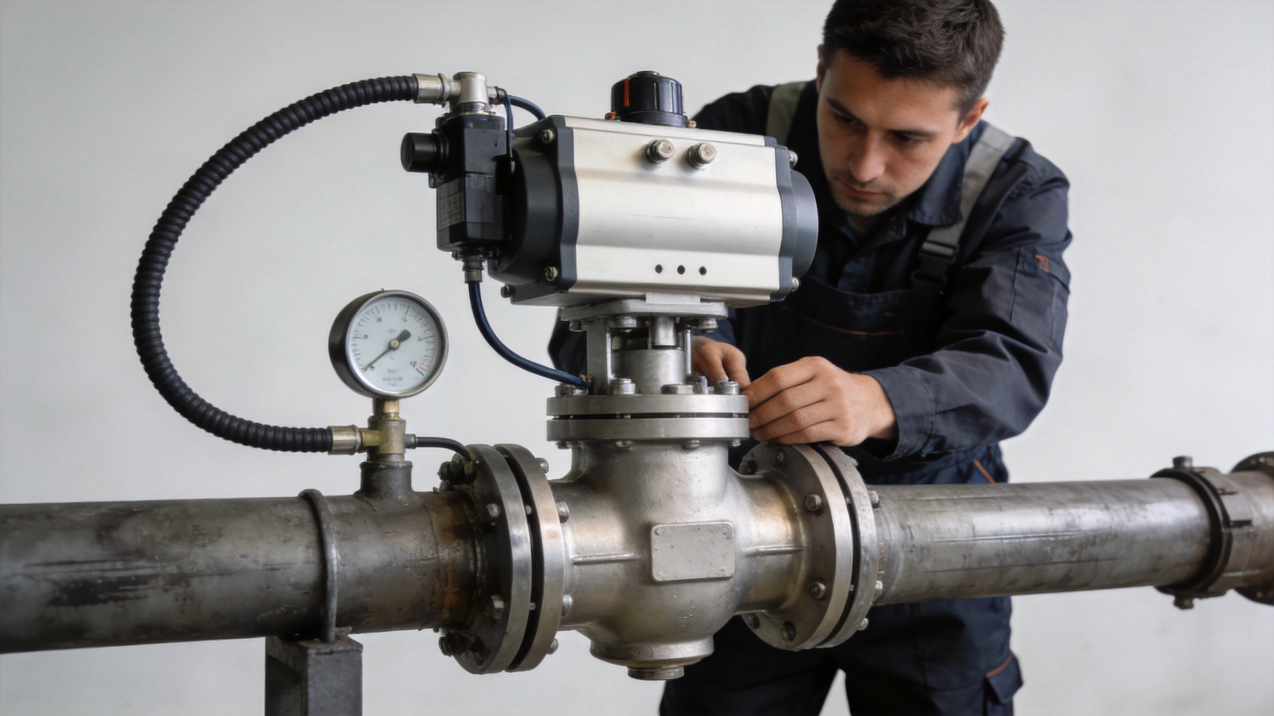
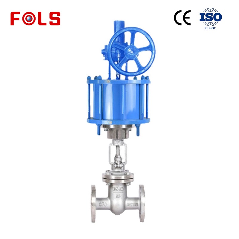
A pneumatic emergency stop valve should be approached as a defined protective function, not simply as a faster Pneumatic Valve. The required final position, response expectation, proof-test approach, air-loss behavior, manual-reset requirements, and upstream/downstream isolation logic all need to be clear. For example, closing on loss of air may be desirable in one service and disruptive in another. The process team should establish the desired state before equipment selection turns that intent into actuator, spring, solenoid, and control-system requirements.
The useful commissioning question is: what does the complete pneumatic emergency stop valve assembly do when each relevant utility or signal is removed? Testing should reflect the site’s approved procedure and actual installed configuration. Avoid treating a component description as evidence of whole-loop performance.
Where a Digital Valve Controller Adds Value
A digital valve controller can improve visibility when the application needs position feedback, diagnostic information, or more controlled travel behavior. Yet a digital valve controller does not compensate for poor air quality, an undersized actuator, excessive valve friction, or unsuitable fail-safe logic. It should be selected around the control objective: simple open/close confirmation, modulating control, stroke monitoring, or planned maintenance insight.
For a heavy-duty Pneumatic Valve, assess the signal type, environmental protection needs, feedback accuracy required by the process, air consumption, local indication, and what alarms the maintenance team can realistically act on. The goal is not to add electronics by default; it is to make the control chain easier to verify and maintain.
A Practical Review Sequence Before Purchase or Upgrade
- Define the medium and duty: include normal and upset conditions, pressure, temperature, flow behavior, and cycle frequency.
- Set the functional state: identify whether the Pneumatic Valve must fail open, fail closed, or hold position, and why.
- Match valve and actuator: review torque or thrust needs across the relevant travel and supply-pressure range.
- Review the air circuit: document filtration, regulation, drainage, tubing, connections, leakage control, and available pressure.
- Confirm interfaces and feedback: verify valve mounting, accessory mounting, solenoid logic, travel indication, and any digital valve controller requirements.
- Plan access and testing: decide how the installed Pneumatic Valve will be inspected, stroked, isolated, and returned to service.
Conclusion
The most reliable way to improve Pneumatic Valve performance in heavy-duty industrial sectors is to evaluate the whole operating chain instead of a single component. Do not first ask which valve is suitable; first write down the medium, pressure, temperature, duty cycle, air conditions, and required failure state. With those conditions clear, teams can compare valve body, actuator, pneumatic emergency stop valve behavior, and digital valve controller options on a basis that is both more practical and easier to verify.
 Hot News





