
 EN
Pneumatic Valve Installation and Setup Operation Guide
Installing a Pneumatic Valve is not only a matter of connecting ports and applying air. A dependable installation starts by confirming the process duty, actuator arrangement, air quality, and machine safety function before anyone opens the supply. This guide gives maintenance teams, machine builders, and industrial buyers a practical sequence for installing, commissioning, and operating a Pneumatic Valve while keeping unknowns visible for engineering review.
In day-to-day valve application work, a useful rule is this: treat the valve body, actuator, air-preparation unit, tubing, controls, and guarded machine area as one system. A Pneumatic Valve that is suitable on paper can still perform poorly if the air supply is contaminated, the actuator has no maintenance clearance, or the fail position is wrong for the process.
1. Confirm the application before installing a Pneumatic Valve
Before mounting a Pneumatic Valve, freeze the information that affects safety and function. Confirm the media, normal and maximum process pressure, temperature, pipe size and connection standard, flow direction where applicable, operating frequency, control signal, and required valve position on loss of air or power. Also verify that the actuator torque or thrust is appropriate for the selected valve body under the actual differential-pressure condition. Do not assume that two valves with the same nominal size or actuator outline have the same operating requirement.
Record whether the actuator is single acting or double acting. A single-acting Pneumatic Valve uses a spring return and therefore has a defined spring-driven position; a double-acting unit needs air to move in both directions. The required safe position should be established by the process and machine risk assessment, not chosen simply because a particular configuration is in stock.
- Compare the valve, actuator, solenoid, fittings, seals, and tubing ratings with the intended duty.
- Confirm port identification and the control schematic supplied for the actual assembly.
- Leave access for manual override, position indication, inspection, and future replacement.
- Identify who approves any change to the pneumatic circuit or safety function.
2. Isolate energy and prepare the compressed-air supply
Lock out the machine according to the site procedure before work begins. Isolate electrical and pneumatic energy, discharge stored pressure where the procedure requires it, and verify the equipment cannot move unexpectedly. Do not rely on a control command alone as proof that a Pneumatic Valve is safe to handle. A cylinder, actuator, or trapped section of hose can retain energy after the upstream source has been closed.
Prepare the air supply upstream of the Pneumatic Valve. The required arrangement varies by machine, but a typical air-preparation path may address shutoff, filtration, regulation, monitoring, soft start, and controlled exhaust. Use clean, dry air consistent with the component documentation. Contamination, water, incompatible lubricants, and an unstable regulator setting can cause delayed response, internal leakage, sticking, or shortened seal life.
Set pressure only after checking the component documentation and the engineering specification. Higher pressure is not automatically better: it can increase actuator force, but it may also exceed limits or change the behavior of the driven equipment. If pressure is adjusted during commissioning, log the final setting and the person who approved it.
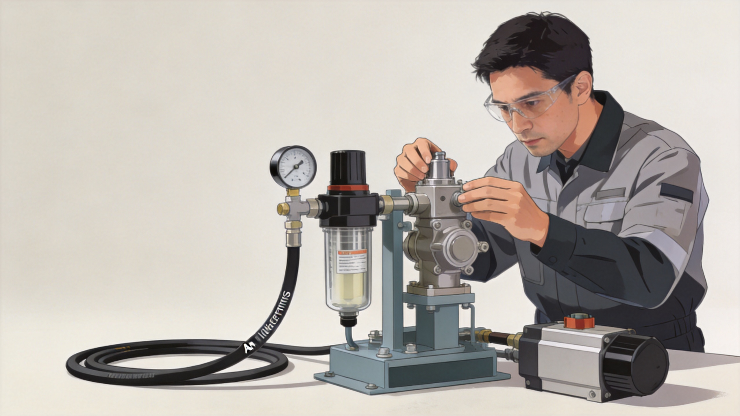
3. Mount the valve body and actuator correctly
Support nearby pipework so its weight, misalignment, vibration, or thermal movement is not transferred into the Pneumatic Valve. Clean the mating surfaces and remove debris from the line before installation. Use the specified gaskets, fasteners, tightening sequence, and torque values from the relevant valve documentation. Avoid using the actuator as a lever to turn or align the assembly.
Orient the Pneumatic Valve so that indicators, cable entries, pilot ports, drains, and manual overrides remain accessible. Where a valve has a marked flow direction, follow it. Where the assembly may collect condensate or contaminants, select an orientation that supports drainage and inspection. They can look minor during installation, yet they often decide whether the assembly remains serviceable or causes a difficult shutdown later.
4. Connect pneumatic lines and control components
Use tubing and fittings that match the air pressure, environment, bend-radius requirement, and port specification. Cut tubing squarely, keep it free of chips, and route it so it cannot rub against moving equipment or become kinked. Before connecting a Pneumatic Valve, verify the port labels against the assembly drawing rather than relying on a generic convention. Misrouted pilot lines can reverse the intended motion or prevent a spring-return actuator from reaching its required position.
Install the solenoid valve, pilot valve, positioner, limit switch, or feedback device only in accordance with the approved circuit. Check electrical supply, signal type, grounding, ingress protection needs, and cable routing before energizing. Where a feedback signal is used, confirm that open/closed indications represent the actual mechanical position—not just the command that was sent.
5. Keep pressure relief and safety dump functions distinct
A pneumatic pressure relief valve and a pneumatic safety dump valve may both appear near an air-preparation system, but they address different hazards. A pneumatic pressure relief valve is generally associated with limiting excessive pressure in a protected portion of a system. Its set pressure, capacity, discharge path, and installation details must be selected for the protected equipment and applicable requirements.
A pneumatic safety dump valve is generally used to isolate and exhaust downstream pneumatic energy in a controlled safety architecture. It is not a substitute for a properly selected pneumatic pressure relief valve, and a relief device is not automatically a machine-energy isolation device. Determine the required safety function, diagnostic coverage, restart behavior, and validation method through the machine’s risk assessment and applicable engineering standards. Do not claim a performance level or certification unless the exact component and completed system design support it.
6. Commission a Pneumatic Valve in stages
Commissioning works best when each observation is deliberate and recorded. Start with a visual inspection: confirm fasteners, tubing, labels, guards, wiring, air preparation, and access. Then introduce air gradually where the approved procedure allows. Listen for leaks and observe the actuator at low-risk conditions. A Pneumatic Valve should move fully to each commanded position without binding, unexpected motion, excessive delay, or interference with surrounding equipment.
- Verify the installed configuration against the drawing and approved bill of materials.
- Apply the specified air pressure and check every fitting and port for leakage using the site-approved method.
- Cycle the Pneumatic Valve at no-load or controlled conditions, observing travel, indication, and fail position.
- Confirm command-to-feedback agreement, interlocks, and permitted restart behavior.
- Test the relevant pneumatic safety dump valve or pneumatic pressure relief valve function only under an approved test procedure.
- Document settings, results, deviations, and unresolved questions before releasing the equipment.
7. Operate and maintain the Pneumatic Valve
During normal operation, monitor cycle behavior, air pressure stability, leakage, contamination, and position feedback. A slow or inconsistent Pneumatic Valve is often a system symptom rather than proof that the valve itself has failed. Check upstream filtration and regulator performance, tubing restrictions, pilot supply, solenoid response, mounting alignment, and the process load before replacing components.
Plan preventive work around actual duty. High-cycle service, dirty environments, outdoor exposure, and frequent pressure changes justify more frequent inspection than a lightly used indoor assembly. Before dismantling a Pneumatic Valve, isolate, lock out, exhaust stored energy, and verify the safe condition again. Replace seals, fittings, or actuators only with parts confirmed for the assembly; undocumented substitutions can change compatibility, operating force, or fail behavior.
Final installation checklist
The aim is a Pneumatic Valve installation that can be documented, tested, and maintained without guesswork. The final handover file should identify the process conditions, valve and actuator configuration, supply pressure, control logic, safety-function boundaries, test results, maintenance access constraints, and contacts for technical clarification. That record gives operators a useful baseline when conditions change—and makes the next intervention safer and faster.
 Hot News





