
 EN
What Is an Electric Valve and How Does It Function?
An Electric Valve is a valve assembly that uses electrical power to move, position, or control a flow path. In industrial piping, the phrase can describe a valve with an electric actuator, a motorized valve, or—less precisely—a coil-operated solenoid valve. Those devices can all influence fluid flow, but they do not use the same mechanism. Knowing the distinction helps engineers, maintenance teams, and buyers ask for the right configuration before a valve is specified.
From an industrial valve application engineer’s perspective, an Electric Valve should first be tied to the medium, pressure, temperature, valve duty, and required control method. The valve body determines how the process stream is handled. The electrical device supplies the motion or command response. A good selection considers both as one system rather than treating the actuator as an accessory added at the end.
What does an Electric Valve do?
At its simplest, an Electric Valve changes the condition of a flow passage when it receives an electrical command. Depending on the design, it may open fully, close fully, stop at a defined intermediate position, or continuously adjust flow. It is used where manual operation would be slow, inaccessible, inconsistent, or difficult to connect with a control system.
The same basic purpose appears in water treatment, HVAC, chemical processing, utility systems, oil and gas support equipment, and automated production lines. However, an Electric Valve is not automatically suitable for every fluid or every control task. The body material, seal material, pressure rating, differential pressure, torque demand, and operating frequency still need to match the application.
The main parts of an electrically controlled valve
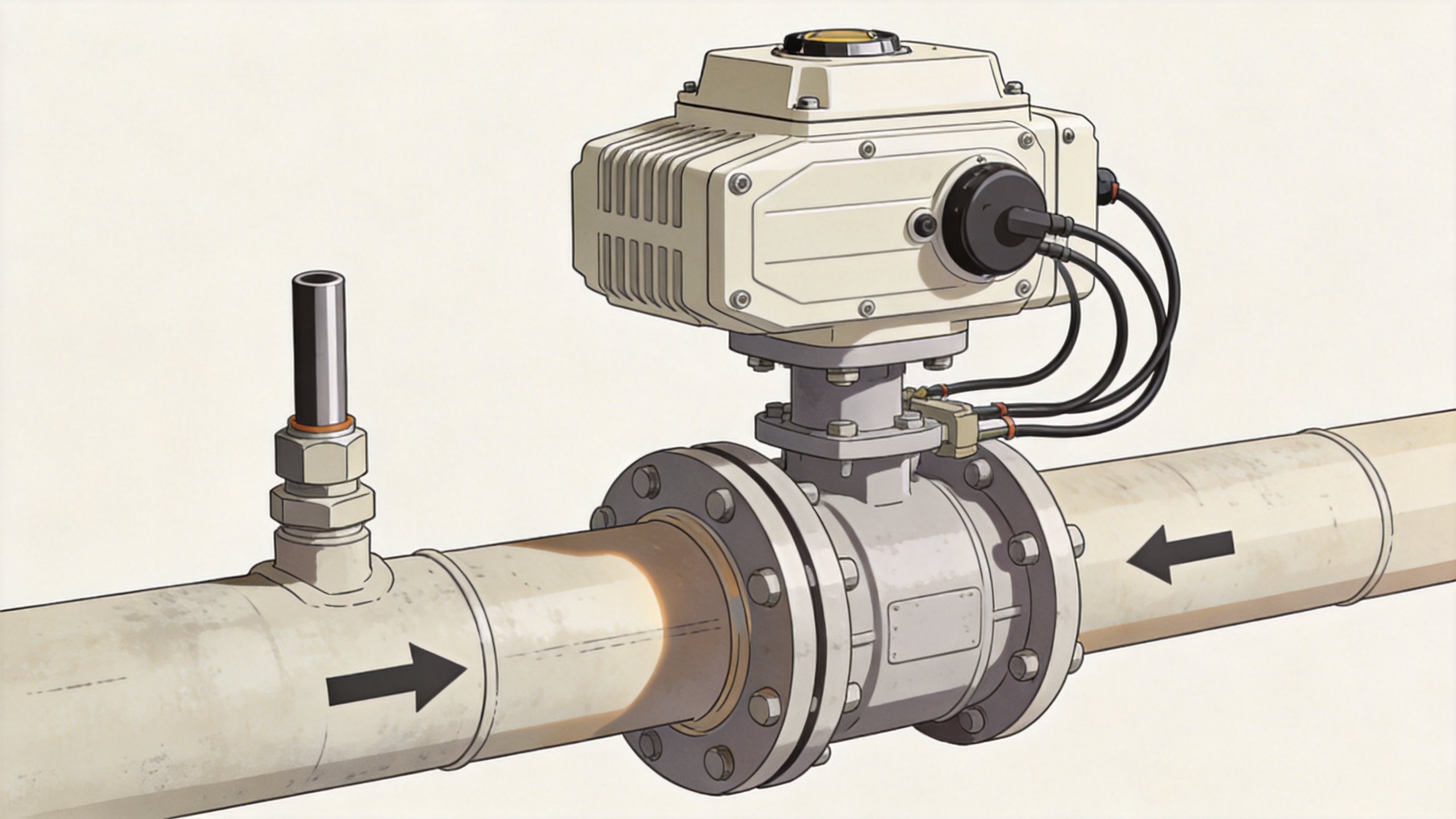
A typical electrically actuated assembly combines several parts:
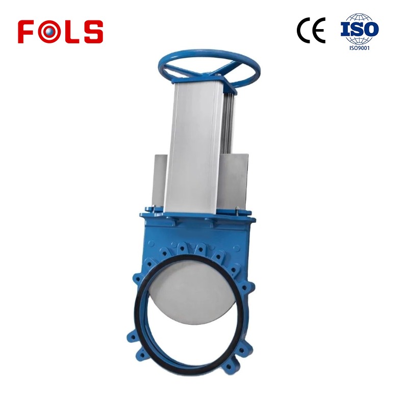
- Valve body: The ball, butterfly, gate, globe, diaphragm, or other closure element that directs the fluid.
- Electric actuator or solenoid coil: The component that converts electrical energy into movement.
- Drive train: In a motorized Electric Valve, gears, shafts, or a screw mechanism transfer motor motion to the stem or shaft.
- Control interface: This can be simple open/close wiring, a relay signal, or a modulating control signal.
- Position feedback: Limit switches, a potentiometer, or another sensor can report whether the valve has reached the commanded position.
- Manual override and enclosure: These features affect serviceability and environmental suitability, but must be confirmed for the selected model.
That division of responsibilities matters. A durable actuator cannot compensate for a valve body that is incompatible with the medium, and a suitable body cannot deliver automated performance if the actuator lacks enough torque or the correct control interface.
How an Electric Valve functions step by step
The exact sequence depends on the design, but a motorized Electric Valve usually works through the following cycle:
- A command arrives. A switch, controller, PLC, thermostat, or other device sends an electrical signal requesting open, close, or a target position.
- The actuator interprets the command. For simple on/off service, the actuator drives in one direction until it reaches an end point. For modulating service, it compares the requested position with actual position and makes corrections.
- The motor produces rotary or linear motion. A gear train often reduces speed and increases usable output torque.
- The valve closure member moves. The actuator turns a ball or butterfly shaft, or moves a stem associated with another valve style. That movement changes the available flow area.
- Feedback confirms travel. End-of-travel limit switches commonly signal fully open or fully closed. More advanced assemblies can return a continuous position signal. A 4–20 mA signal is one common convention for modulating controls, but the signal type must be verified against the actual actuator specification.
- The drive stops or holds position. The actuator stops at the required travel limit or maintains the commanded setting according to its design.
In other words, an Electric Valve translates an electrical request into controlled mechanical travel and then into a change in flow. The process sounds direct, yet response time, available torque, valve friction, process pressure, and control accuracy can all affect the outcome.
Electric actuator versus solenoid operation
The terms are often mixed, especially in quick product searches. A motorized Electric Valve uses an electric motor and mechanical drive to operate the valve. It is commonly selected when the valve needs more travel, greater torque, staged motion, or feedback. A motorized ball or butterfly valve is a familiar example.
An electric solenoid hydraulic valve, by contrast, uses an electromagnetic coil to shift a plunger, poppet, or spool. In hydraulic circuits, this action may directly control a small passage or pilot another function. A solenoid can react quickly and works well for many directional or pilot-control duties, but it is not simply a smaller version of a motorized actuator. The required force, travel, fluid circuit, and failure mode can be very different.
An electric solenoid actuator should therefore be evaluated by its intended valve and control function. Before comparing labels, confirm whether the process needs direct coil action, pilot operation, quarter-turn motor torque, multi-turn travel, or a modulating control loop.
Common Electric Valve control modes
On/off control
An on/off Electric Valve moves between defined open and closed positions. It fits isolation, filling, draining, sequencing, and many interlock functions. The important questions are not just “open or close?” but how often the command is issued, how fast motion is required, and what should happen if power is interrupted.
Modulating control
A modulating Electric Valve can move to intermediate positions to help regulate flow, pressure, temperature, or level. Position feedback becomes more important because the controller needs a reliable relationship between its command and actual valve travel. For this duty, valve sizing and the selected flow characteristic also deserve attention; actuator control alone does not guarantee stable process control.
Fail-position and safety behavior
Some applications need the valve to remain in place during a loss of power; others require it to move toward a predefined safe condition. Do not assume that every Electric Valve is fail-open or fail-closed. The actuator design, stored-energy feature if any, wiring arrangement, and process hazard review determine the appropriate choice.
How to choose an Electric Valve
Do not begin with a product name alone. Start with the operating conditions. A practical confirmation list includes:
- What medium flows through the valve, and is it clean, corrosive, viscous, abrasive, or temperature-sensitive?
- What are the normal and maximum pressure and temperature conditions?
- Is the required action on/off, throttling, diverting, or directional hydraulic control?
- How often will the Electric Valve cycle, and how much operating time is available for each stroke?
- What valve type, size, connection, seal, and body material are compatible with the line?
- What electrical supply, signal type, enclosure, and feedback are needed at the installation point?
- Does the actuator have sufficient output torque or thrust under the expected differential pressure and friction conditions?
- What manual operation, inspection space, and maintenance access will be available after installation?
Do not first ask which valve is “better.” First write down the medium and control conditions. A single torque figure is useful, but it matters more whether that torque matches the valve, pressure differential, service condition, and required safety margin. This is where an Electric Valve selection becomes a system decision rather than a catalog comparison.
Installation and maintenance considerations
Before commissioning an Electric Valve, verify the permitted mounting orientation, electrical protection requirements, wiring diagram, travel limits, and direction of operation. Where feedback is used, test the reported position against actual valve movement. Where the valve is part of an automated sequence, test the command logic and interlocks under controlled conditions.
Routine maintenance should focus on the conditions that influence movement: loose terminals, damaged cable entries, water ingress, unusual noise, rising operating time, excessive heat, stem or shaft resistance, and leakage around the valve. The inspection interval should reflect the actual service, not a generic calendar promise. If a valve begins to stall or repeatedly trips, verify process conditions and mechanical resistance before assuming that the electrical actuator alone is at fault.
Key takeaway
An Electric Valve uses electrical energy to operate a valve and manage fluid flow, but the exact mechanism may be motorized, solenoid-driven, or part of a more complete automated control assembly. The most reliable way to specify one is to match the valve body, actuator type, control signal, torque or thrust requirement, feedback need, and safety behavior to the real operating conditions. When those details are confirmed early, the resulting Electric Valve is easier to integrate, operate, and maintain.
 Hot News





