
Match Core Operating Conditions to Pneumatic Valve Specifications
Selecting industrial pneumatic valves begins with rigorous assessment of four fundamental parameters: fluid media compatibility, operating pressure range, temperature limits, and flow capacity. Valves exposed to incompatible fluids risk seal degradation and corrosion—air-operated systems typically require EPDM or Nitrile seals, while chemical processes demand Viton® or PTFE. Pressure specifications must encompass both steady-state operations and surge events; exceeding rated limits compromises valve integrity, as seen in hydraulic hammer scenarios where transient spikes exceed 150% of working pressure. Temperature equally impacts material resilience—standard elastomers fail below –20°C (–4°F) or above 100°C (212°F), necessitating specialty polymers for extreme conditions. Critical to efficiency is flow capacity quantification via Cv values; undersized valves create flow restrictions that increase energy consumption by 15–25%, while oversized units cause control instability.
Fluid media, pressure range, temperature limits, and flow capacity (Cv) alignment with process demands
Precisely match valve materials to media properties—brass valves suffice for dry air, but stainless steel becomes essential with corrosive gases or liquids. Pressure ratings should incorporate safety margins of 25–50% above maximum operating conditions, with pulsating systems requiring fatigue-resistant designs. Temperature tolerance must cover thermal cycling extremes; aerospace applications often demand –54°C to +204°C (–65°F to +400°F) ranges. Flow capacity analysis using Cv coefficients prevents turbulence: calculate required Cv using Q = Cv √(ΔP/SG), where Q is flow (GPM), ΔP is pressure drop (psi), and SG is specific gravity. Oversized Cv values above 2.0 in precision applications cause hunting and wasted air.
Environmental compliance: IP rating, explosion protection (Ex d/Ex i), and ATEX/IECEx zone classification
Industrial environments dictate specialized certifications to mitigate hazards. Ingress Protection (IP) ratings determine dust/water resistance—IP65 withstands hose-directed water, while IP67 allows temporary submersion. Hazardous locations mandate explosion-proofing: Ex d (flameproof enclosure) valves contain internal blasts, while Ex i (intrinsic safety) limits electrical energy to prevent ignition. Per IEC 60079 standards, ATEX/IECEx zone classifications define risk levels—Zone 1 (explosive atmospheres occasionally present) requires Category 2G valves with redundant safety controls. Food and pharmaceutical sectors often need FDA-compliant materials and cleanroom-rated designs. Ignoring certifications risks regulatory penalties averaging $87,000 (OSHA 2023) and catastrophic failures in volatile settings.
Evaluate Valve Type and Configuration for Control Functionality and Safety
Directional Control Valve Configurations (2/2, 3/2, 5/3) and Their Impact on Machine Safety Logic and Circuit Design
Selecting the correct directional control valve configuration directly determines fail-safe operation and emergency response effectiveness. A 3/2 valve enables single-acting cylinder control with automatic spring return—critical for safety-critical ejector systems where unintended extension poses hazards. Complex machinery using 5/3 valves maintains mid-position stability during power loss, preventing uncontrolled actuator drift. Misalignment between valve function and safety logic circuits increases fault risks by 47%, per ISA TR84.00.02-2021, particularly in automated production lines where sequential operations demand precise port sequencing.
Comparative Performance: Ball, Butterfly, and Angle Seat Pneumatic Valves in Speed, Regulation Accuracy, and Pressure Drop
Valve type dictates process efficiency through three performance vectors:
- Ball valves achieve 90° shut-off in under 0.5 seconds but struggle with flow modulation below 30% of Cv
- Butterfly valves offer less than 1.5% regulation error at partial loads yet incur 15–30% higher pressure drops than angle seat valves
- Angle seat valves combine low hysteresis (<0.8%) with linear flow characteristics, making them ideal for dosing systems requiring ±2% accuracy
While ball valves dominate quick isolation tasks, angle seat designs reduce energy losses by 22% in throttling applications, according to compressed air audits (2023). Match response speeds and turndown ratios to your automation timing requirements—high-speed packaging demands faster actuation than batch processing systems.
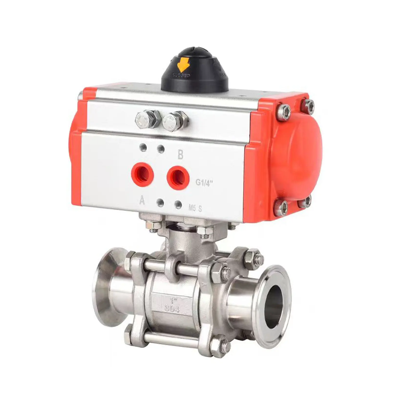
Ensure Mechanical and Actuation Compatibility for Reliable Integration
Matching physical interfaces and actuation methods prevents operational failures in pneumatic systems. Proper integration eliminates leaks, pressure drops, and mechanical stress during valve operation.
Connection standards (NPT, BSP, ANSI, DIN), port sizing, and mounting interface consistency with existing infrastructure
Valve connection standards must align with existing infrastructure: NPT (tapered threads for North America), BSP (parallel threads common in Europe), ANSI (flanged connections), or DIN (metric standardization). Port sizing directly impacts flow efficiency—undersized ports cause flow restrictions, while oversized ports increase costs without performance gains. Mounting interfaces (bolt patterns, bracket designs) require physical compatibility with machinery frames. A 2023 fluid power industry analysis found 65% of pneumatic system failures originated from mismatched connections, emphasizing dimensional verification during procurement.
Actuator selection: single-acting vs. double-acting, fail-safe behavior, and solenoid/manual/pneumatic operation trade-offs
Actuator choice balances safety, efficiency, and control:
- Single-acting: Uses spring return for fail-safe closure during air failure. Lower air consumption but reduced force output.
-
Double-acting: Higher force and speed with bidirectional air pressure. Requires additional valves for fail-safe positioning.
Operation modes present trade-offs: - Solenoid enables rapid automated control but depends on electrical systems.
- Manual overrides support maintenance yet limit responsiveness.
- Pneumatic actuation excels in explosive environments but has slower cycle times.
A 2024 automation reliability study showed double-acting actuators reduced cycle times by 22% in high-speed applications, while single-acting designs dominated safety-critical processes. Select based on fail-safe requirements and energy constraints.
FAQs About Pneumatic Valves
What are the key parameters for selecting industrial pneumatic valves?
Fluid media compatibility, operating pressure range, temperature limits, and flow capacity are the key parameters when selecting industrial pneumatic valves.
Why is matching the valve material to media properties important?
It prevents corrosion and ensures optimal performance by choosing the right materials for the specific type of media being handled.
How do you calculate the required Cv value?
Use the formula Q = Cv √(ΔP/SG), where Q is flow in gallons per minute, ΔP is pressure drop in psi, and SG is specific gravity.
What environmental compliance standards should pneumatic valves meet?
Pneumatic valves should meet IP ratings, explosion protection standards, and ATEX/IECEx zone classifications based on the industrial environment.
What role does actuator selection play in pneumatic valves?
Actuator selection influences safety, efficiency, and control. It determines how the valve will respond during failures and operational cycles.
Table of Contents
- Match Core Operating Conditions to Pneumatic Valve Specifications
- Evaluate Valve Type and Configuration for Control Functionality and Safety
- Ensure Mechanical and Actuation Compatibility for Reliable Integration
-
FAQs About Pneumatic Valves
- What are the key parameters for selecting industrial pneumatic valves?
- Why is matching the valve material to media properties important?
- How do you calculate the required Cv value?
- What environmental compliance standards should pneumatic valves meet?
- What role does actuator selection play in pneumatic valves?

